Table of Contents
What Is a Hydraulic Fitting Crimper?
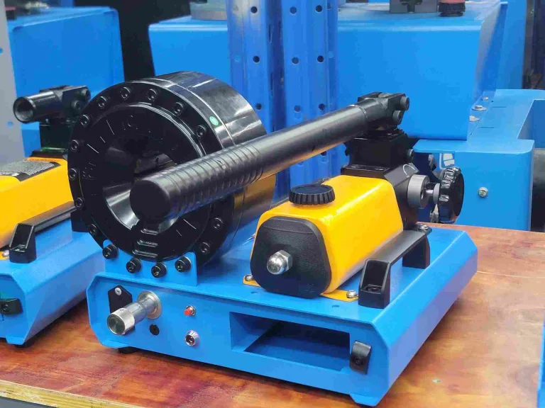
A hydraulic fitting crimper compresses a metal ferrule around a hydraulic hose and fitting to form a permanent, leak-proof seal. The tool uses crimping pressure to push segmented dies inward, reducing the ferrule diameter until it bonds with the hose reinforcement. This is the standard assembly method for hydraulic hose crimper systems worldwide.
On Reddit, a user in r/Hydraulics asked about a simple fitting crimper for home use: “I’m looking for a decent at-home hydraulic hose fitting crimper for 1/4″ to 1″ hose.” The thread drew 10+ replies — most recommended matching the die set to the specific fitting brand rather than buying a generic tool.
That advice is correct. The fitting type dictates the die profile. Use the wrong die, and the crimp will either fail under pressure or damage the fitting. This guide covers the matching logic.
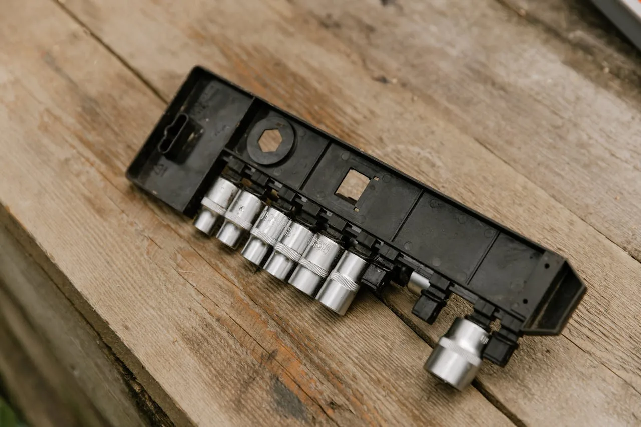
5 Fitting Types You Will Encounter
Before you pick a hose fitting crimper, you need to know which fitting profile you are crimping. Each type has a specific ferrule shape, wall thickness, and crimp specification. Whether you use a hydraulic fitting press or a hydraulic hose fitting crimper, the fitting type always dictates the die profile.
| Fitting Type | Structure | Pressure Range | Common Use |
|---|---|---|---|
| One-piece | Ferrule and stem are a single unit | Up to 420 bar | Most OEM assemblies |
| Interlock | Ferrule locks over the stem with a collar | Up to 700 bar | High-vibration applications |
| Reusable | Two-piece, field-attachable, no crimping needed | Up to 210 bar | Emergency repairs |
| BSP threaded | One-piece with BSP thread end | Up to 350 bar | European equipment |
| SAE flange | Flanged head, bolt-on connection | Up to 420 bar | Large-diameter hoses (2″+) |
One-piece and interlock fittings account for about 85% of all hydraulic assemblies. Both require a crimper dies set matched to the manufacturer’s specification sheet. See Wikipedia: Piping Fittings for a broader overview of fitting types.
One-Piece vs Interlock: Why It Matters for Your Die
A one-piece fitting has a smooth outer ferrule. The die compresses it uniformly. An interlock fitting has a visible collar that folds inward during crimping — the die must have a step profile to accommodate this extra material. If you use a flat-profile die on an interlock fitting, the collar will not fold, and the assembly will fail at pressures above 280 bar.
This is the single most common mistake when shops switch fitting suppliers. The hydraulic fitting crimping tool stays the same, but the die changes.
Die-to-Fitting Compatibility Table
Below is the compatibility matrix for the 9 standard die series used with hydraulic crimper machines. TRC produces dies in all 9 series for its full product line.
| Die Series | Fitting Type | Hose Size Range | Profile | Steel Grade |
|---|---|---|---|---|
| G7 | One-piece (straight/45°/90°) | ¼″–2″ | Flat | Cr12MoV |
| G8 | Interlock (all angles) | ¼″–2″ | Step | Cr12MoV |
| X35 | One-piece (metric) | 6–51mm | Flat | Cr12MoV |
| X36 | Interlock (metric) | 6–51mm | Step | Cr12MoV |
| UN24 | Parker-style one-piece | ¼″–2″ | Flat | Cr12MoV |
| UN25 | Gates-style one-piece | ¼″–2″ | Flat | Cr12MoV |
| FC21 | Flange (SAE) | 1″–4″ | Deep pocket | Cr12MoV |
| NC20 | Nut crimp (fine-blank) | 6–42mm | Flat + locator | Cr12MoV |
| SK10 | Special (ball-type) | ¼″–1″ | Custom | Cr12MoV |
All TRC dies are hardened to HRC 58–62 using Cr12MoV tool steel. The die seat (the ring that holds the dies) must maintain hardness ≥ HRC 60 to prevent deformation under repeated load cycles. This dual-hardness standard — die ≥ HRC 50, die seat ≥ HRC 60 — is the baseline for producing roundness and taper within 0.1mm, as required by ISO 8434 for hydraulic fitting assemblies.
How to Calculate Crimp Diameter
Every fitting manufacturer publishes a crimp specification sheet. It lists the target crimp diameter for each hose-fitting combination. Here is the formula:
Target Crimp Diameter = Ferrule OD before crimp − (2 × Die Compression Depth)
In practice, you look it up rather than calculate. The specification sheet tells you the exact diameter to hit, typically measured with a vernier caliper accurate to 0.02mm. TRC’s tolerance is ±0.03mm (industry average is ±0.125mm).

3 Measurement Points After Crimping
- Ferrule mouth — Should show visible compression marks. No gap between ferrule and hose outer cover.
- Ferrule center — Measure here with calipers. Must be within ±0.03mm of the spec sheet value.
- Ferrule tail — Should grip the hose tightly. If you can spin the hose, the crimp is too loose.
A user on r/Hydraulics reported: “I bought some ¼ Vevor hydraulic hose off Amazon and some JIC -4 crimps. The dies are off.” This is a classic die-fitting mismatch — the crimper was fine, but the die cavity did not match the ferrule profile of that specific fitting brand.
First-piece inspection rule: after calibrating the die for a new hose-fitting combination, crimp one test piece and measure the actual crimp diameter. The result must fall within the window of (minimum crimp size + 0.05mm) to (maximum crimp size − 0.05mm). If it falls outside this window, recalibrate before running production.
9 Die Series Explained
When you buy a electric hydraulic hose crimper, it typically comes with 10–14 die sets in one or two series. Here is what each series covers:
| Series | Best For | Hose Standards | Die Count |
|---|---|---|---|
| G7 | Standard one-piece fittings (DIN) | DIN EN 853, ISO 1436 | 14 sizes |
| G8 | Interlock fittings (DIN) | DIN EN 856, ISO 3862 | 14 sizes |
| X35 | Metric one-piece | SAE J517, DIN EN 853 | 12 sizes |
| X36 | Metric interlock | SAE J517, DIN EN 856 | 12 sizes |
| UN24 | Parker-type OEM replacements | SAE J517 | 14 sizes |
| UN25 | Gates-type OEM replacements | SAE J517 | 14 sizes |
| FC21 | Large SAE flanges | SAE J518 | 6 sizes |
| NC20 | Fine-blank nut crimping | Custom | 10 sizes |
| SK10 | Ball-type special fittings | Custom | 8 sizes |
The two most common die series — G7 and UN24 — cover about 70% of all field crimping work. If you are starting a manual hydraulic hose crimper kit, buy G7 first and add other series as you encounter different fitting brands.
4 Matching Errors That Cause Leaks
1. Wrong Die Profile on Interlock Fittings
Using a flat-profile G7 die on an interlock fitting. The collar will not fold, leaving a gap between the ferrule and the stem. The assembly holds at low pressure but fails above 280 bar. Always check if the fitting has a visible collar — if it does, use a step-profile die (G8 or X36).
2. Die Wear Beyond 10,000 Cycles
Dies lose their edge over time. After approximately 10,000 cycles, the die cavity expands by 0.05–0.10mm due to metal fatigue. This produces under-crimped assemblies. Measure your crimp diameter regularly. If it drifts more than 0.05mm above spec, replace the die.
Beyond die wear, check the zero-taper crimping condition: the front and rear of the ferrule must compress by the same amount. If the machine has taper, the ferrule compresses more at one end — causing either pull-out risk (under-crimped end) or inner-tube damage (over-crimped end). TRC machines use a no-cumulative-error machining process on the die seat to maintain zero-taper across all 8 die segments.
TRC dies use Cr12MoV hardened to HRC 58+ for longer life — see the crimper dies and accessories page for replacement options.
3. Mixing Fitting Brands Within One Die Set
Parker and Gates fittings have similar outer dimensions but different ferrule wall thicknesses. A die calibrated for a Parker -8 fitting will under-crimp a Gates -8 fitting by 0.15mm. That is enough to cause a slow leak at working pressure. Use the die series matched to the fitting brand (UN24 for Parker, UN25 for Gates).
4. Skiving Errors Affecting Crimp Quality
If the hose is not skived to the correct length, the ferrule will grip rubber instead of the wire braid. The crimp looks fine but has no mechanical lock. For wire-braid hoses (DIN EN 853, SAE J517), external skiving is required for most one-piece fittings. Use a hose skiving machine to strip the outer cover to the exact length specified in the fitting datasheet.

Which Crimper Matches Your Fittings?
Not every crimping tool for hydraulic fittings handles every die series. Here is a quick selection guide based on machine type:
| Machine Type | Die Series Supported | Best Fitting Range | Model Example |
|---|---|---|---|
| Manual (hand pump) | G7, G8, X35 | One-piece + interlock, ¼″–1½″ | P16HP |
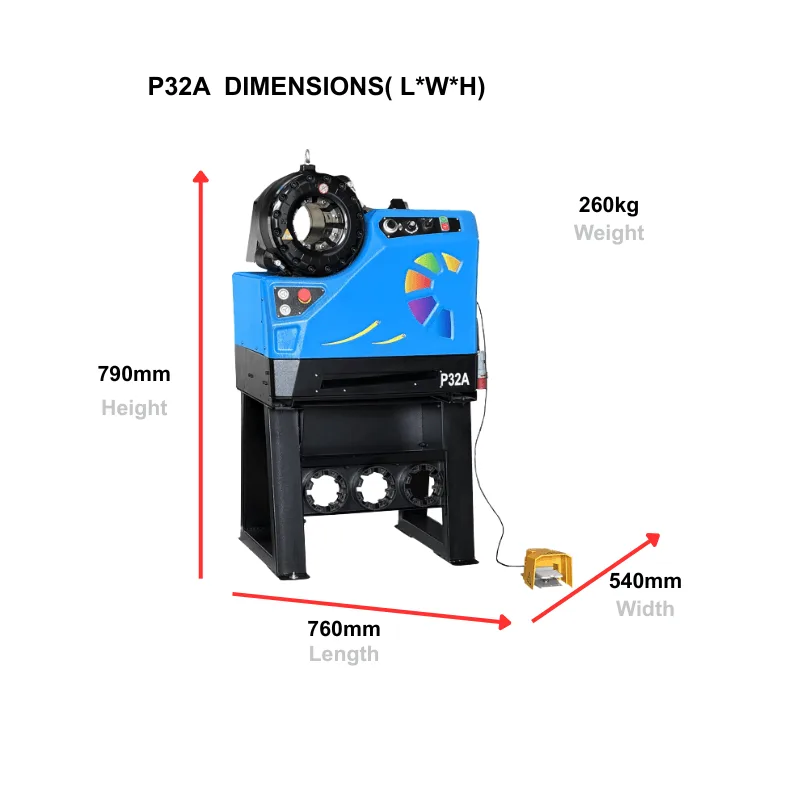
| Electric (bench-top) | All 9 series | Full range, ¼″–2″ | P32A |
| Portable (battery) | G7, G8, X35 | Field one-piece, ¼″–1″ | P20CS |
| Heavy-duty (CNC) | All + FC21 | Flange + large-bore, 2″–6″ | 120L |
For shops running 50+ crimps per day, a electric hydraulic hose crimper with automatic die recognition is worth the investment. The machine reads the die ID and loads the correct crimp specification — no manual lookup needed. See the crimping machine guide for a detailed breakdown.
Need the Right Die for Your Fittings?
TRC stocks 150+ die sets across all 9 series. Send us your fitting part numbers and we will match the dies.
Frequently Asked Questions
Can one hydraulic fitting crimper handle all fitting types?
Yes, if it supports multiple die series. A bench-top electric crimper like the P32A accepts all 9 die series, covering one-piece, interlock, flange, and special fittings. Manual and portable models typically support 2–3 series.
How do I know which die series to use?
Check the fitting manufacturer’s datasheet. It specifies the die series and target crimp diameter. If the datasheet is unavailable, measure the ferrule OD and compare it against the die cavity dimensions in the crimper’s manual.
What happens if I use the wrong die?
Three outcomes: under-crimp (leak at working pressure), over-crimp (hose reinforcement damaged, burst risk), or fitting deformation (thread damage on BSP or SAE flange types). All three are dangerous in high-pressure systems.
Do I need different dies for DIN and SAE fittings?
Yes. DIN (metric) fittings use X35/X36 die series. SAE (imperial) fittings use G7/G8 or UN24/UN25. The ferrule dimensions differ even for the same nominal hose size.
How often should I replace crimping dies?
Every 5,000–10,000 cycles, or when crimp diameter drifts more than 0.05mm from spec. TRC dies in Cr12MoV at HRC 58–62 typically last 8,000+ cycles in normal shop conditions. The nut crimping machine NC series uses the same steel grade for consistent die life.
Can I crimp stainless steel fittings with standard dies?
No. Stainless ferrules have higher hardness and require dies with wider cavities to account for reduced compression. Using standard dies on stainless fittings leads to over-crimp and die damage. Contact the die manufacturer for stainless-specific profiles.
What is the tolerance for a correct crimp?
TRC’s production tolerance is ±0.03mm. The industry average is ±0.125mm. For critical applications (mining, marine), the tighter tolerance reduces the failure rate by an estimated 60%. Always measure with a vernier caliper after every crimp.
Do I need to skive the hose before crimping?
For one-piece fittings on wire-braid hoses (DIN EN 853 / ISO 8434), external skiving is required. For interlock fittings and spiral hoses (DIN EN 856), skiving depends on the fitting design — check the datasheet.
Can a manual crimper produce the same quality as an electric one?
Yes, for the crimp itself. The die does the work, not the power source. However, manual crimpers have slower cycle times (15–30 sec vs 6–10 sec), and operator fatigue can cause inconsistent crimp force after 20–30 assemblies. For production volumes above 50 per day, electric hydraulic hose crimper machines are more consistent.