How to Crimp Hydraulic Hose Fittings: Step-by-Step Guide (5 Steps)
| Parameter | Details |
|---|---|
| Process | Radial compression of ferrule onto hose |
| Tolerance | ±0.05mm crimp diameter |
| Die Steel | Cr12MoV, HRC 58-62 |
| Measurement Tool | Vernier caliper (0.02mm resolution) |
| Hose Standards | SAE J517, DIN EN 853/856, ISO 1436/3862 |
| Fitting Standards | ISO 8434, SAE J514 |
| Hydraulic Oil | 68# anti-wear hydraulic oil |
| System Pressure | Up to 31.5 MPa |
| Die Lifespan | 5,000-10,000 cycles |
Table of Contents
What Does It Mean to Crimp Hydraulic Hose Fittings?
Crimping hydraulic hose fittings is the process of permanently attaching a metal fitting to a hydraulic hose using radial compression. A hydraulic hose crimper forces hardened steel dies inward, squeezing the ferrule around the hose until it forms a cold-weld bond between the ferrule, the hose’s wire reinforcement layer, and the fitting stem.
This bond must hold under extreme conditions. A typical hydraulic system runs at 21-35 MPa (3,000-5,000 PSI). If the crimp fails, the fitting blows off — and hydraulic fluid at that pressure can inject through skin, destroy equipment, and shut down operations for hours.
According to crimp joining principles, the radial deformation creates a mechanical interlock between the ferrule’s inner surface and the hose’s wire braid or spiral layer. The compression also creates friction between all contact surfaces, preventing the fitting from pulling out under load.
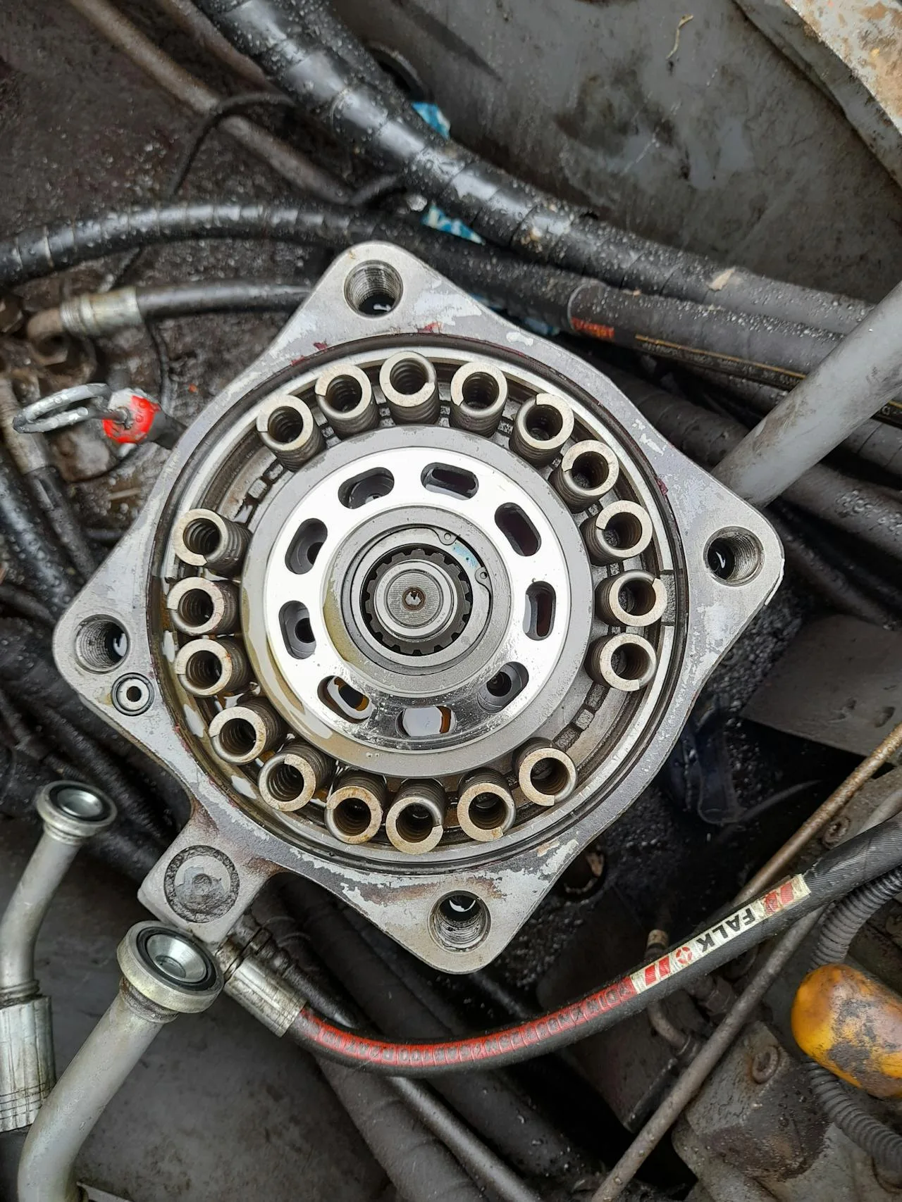
Tools You Need Before You Start
Before you crimp hydraulic hose fittings, gather everything. Stopping mid-process ruins assemblies.
Required Equipment
- Hose crimper — Bench or portable unit with correct tonnage for your hose size. See the full crimper lineup for options.
- Die set — Matched to your hose dash size, construction, and fitting type. Die steel should be Cr12MoV or SKD11 at HRC 58-62. Browse dies and accessories.
- Hose cutting saw — Abrasive wheel or diamond blade for clean, square cuts.
- Skiving machine — Required for spiral hose and interlock fittings. A dedicated skiving machine gives consistent results.
- Vernier caliper — 0.02mm resolution for measuring crimp diameter.
- Tape measure or ruler — For marking insertion depth and skiving length.
- 68# anti-wear hydraulic oil — For the crimper’s hydraulic system.
Safety Gear
- Safety glasses with side shields
- Cut-resistant gloves (handling cut hose ends — wire edges are razor sharp)
- Metal dust mask (when abrasive cutting)
Step 1: Measure and Mark the Hose
Cut the hose to length, accounting for the fitting insertion depth. Measure from the end of the hose to where the ferrule will sit. For most fittings, add 25-40mm to your finished assembly length to account for the portion that goes inside the fitting.
Mark the skiving length on the hose outer cover. This length should match the ferrule length exactly. Mark the insertion depth on the hose — this tells you how far the fitting stem goes in.
Step 2: Cut the Hose Clean and Square
Use a dedicated hose cutting machine with the correct blade type. For 1-wire and 2-wire braided hose (DIN EN 853 / SAE J517), a rotary metal blade at 2,000-3,000 RPM gives a clean cut in 3-5 seconds. For 4-spiral and 6-spiral hose (DIN EN 856), use a diamond-coated blade or abrasive wheel.
The cut must meet these standards:
- Square tolerance: Cut face perpendicular to the hose axis within 1.5°
- Wire flush: Wire reinforcement must be flush with the cut face — not protruding (blocks fitting insertion) or recessed (weak grip)
- Inner tube round: No deformation, no oval shape
- No loose wires: Frayed wires mean a dull blade or wrong speed
About 15% of premature hose failures trace back to poor cutting. A crooked cut means the fitting sits at an angle, creating uneven crimp pressure and a leak path.
Step 3: Skive the Hose (When Required)
Not every hose needs skiving. But getting this wrong is one of the most common mistakes when you crimp hydraulic hose fittings.
When You Must Skive
| Hose Type | Standard | Skive Required? |
|---|---|---|
| 4-spiral (4SP) | DIN EN 856 | Yes — always |
| 4-spiral (4SH) | DIN EN 856 | Yes — always |
| R12 / R13 / R15 | SAE 100R12/R13/R15 | Yes — always |
| Interlock fittings on any hose | — | Yes — always |
| 2-wire braid (2SN) | DIN EN 853 | Usually no with one-piece |
| 1-wire braid (1SN) | DIN EN 853 | Usually no |
Skiving removes the outer rubber cover to expose the wire reinforcement layer. Why? Because rubber compresses over time (creep). If the ferrule grips rubber instead of wire, the bond loosens under vibration and pressure cycling. The ferrule can slide off.
External skiving exposes the wire braid or spiral for the ferrule to grip directly. Internal skiving removes the inner rubber to let the fitting stem seat fully without a gap. Gap = leak starting point.
Depth control is the key variable. Skiving too deep cuts into the wire layer, reducing tensile strength. Too shallow leaves rubber residue between ferrule and wire — weak grip. Use a calibrated skiving machine with adjustable blade position for consistency.
Step 4: Insert the Fitting
Push the fitting stem into the hose until it bottoms out. The insertion depth must match the manufacturer’s specification — typically marked on the fitting or listed in the crimp data sheet.
Four Fitting Types and Their Crimp Differences
One-Piece Fittings
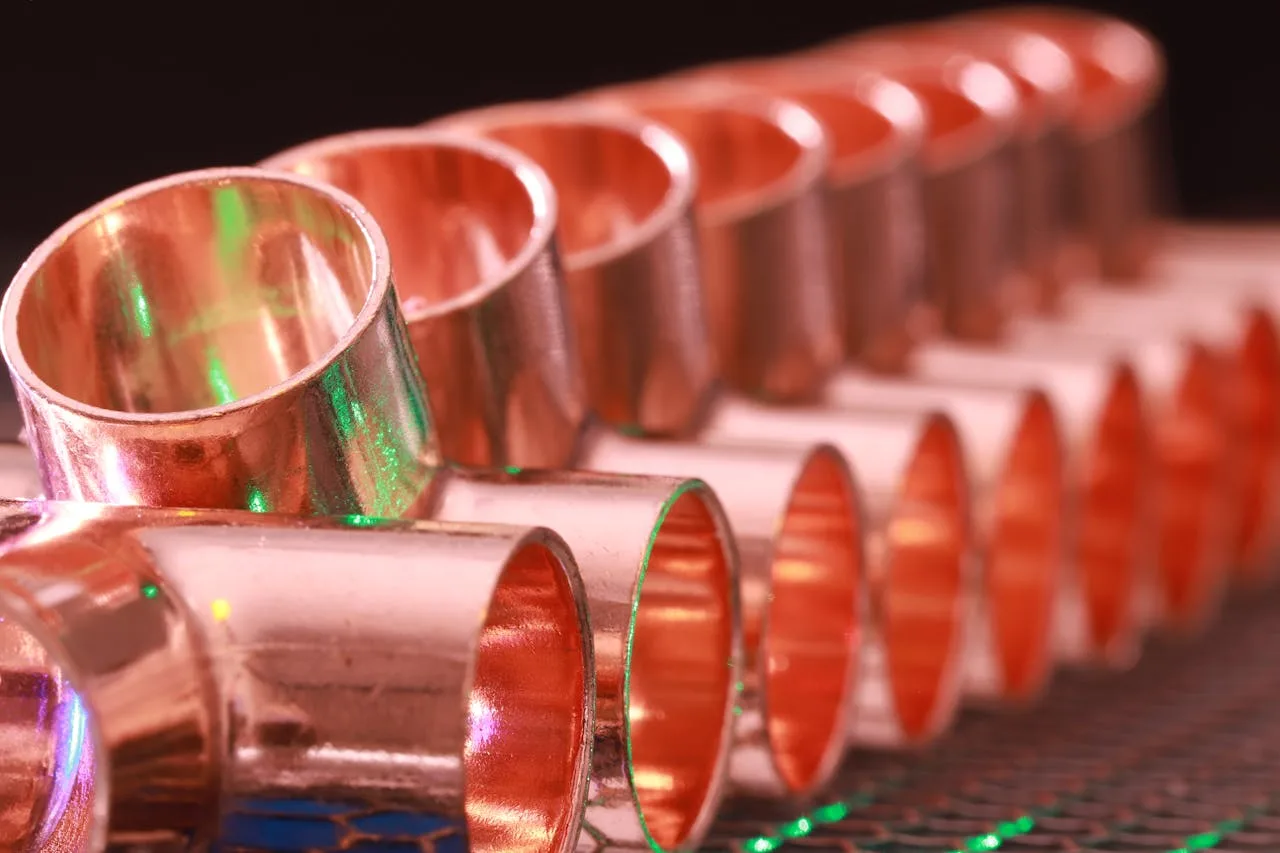
The ferrule and stem are a single unit. You push the hose in and crimp. Simplest to install, most common in general-purpose applications. Works well on braided hose up to 1-1/4″ without skiving on 2SN constructions. The crimp dies compress the ferrule directly onto the hose and wire layer.
Interlock (Two-Piece) Fittings
Separate ferrule and stem. You slide the ferrule onto the hose first, insert the stem, then position the ferrule over the stem’s barbed end. The crimp squeezes the ferrule so it sandwiches the hose from both sides — ferrule outside, stem inside. This gives higher pull-out resistance, which is why interlock fittings dominate spiral hose applications above 25 MPa working pressure.
Reusable Fittings
No crimping required. These use a threaded nut or bolt-together design that clamps onto the hose mechanically. You can remove and reinstall them. Common in field repair situations where a portable crimper isn’t available. The trade-off: lower pressure rating and higher cost per fitting.
Staple-Type Fittings
Used on very large-diameter hose (2″ and above). A staple or pin locks the stem inside the ferrule after insertion. Some staple fittings require crimping the ferrule after stapling; others rely purely on the mechanical lock. Check the manufacturer’s data sheet.
Step 5: Crimp the Assembly
This is where precision matters. Every hundredth of a millimeter counts.
Dies and Accessories Selection
Select the correct die set based on this workflow:
- Identify hose construction (1-wire, 2-wire, 4-spiral, 6-spiral)
- Identify fitting type (one-piece, interlock, reusable, staple)
- Identify hose dash size (-6 = 3/8″, -8 = 1/2″, -12 = 3/4″, -16 = 1″, etc.)
- Look up the fitting manufacturer’s crimp data sheet for target diameter
- Select the die number that matches your hose-fitting combination
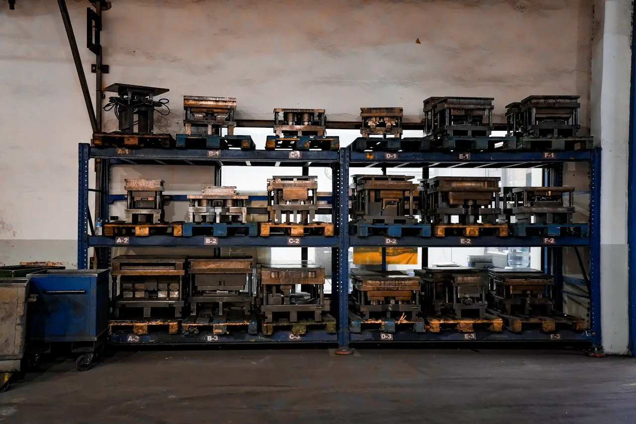
Die steel matters. Cr12MoV at HRC 58-62 is the standard — hard enough to resist deformation, tough enough not to crack. Below HRC 58, the die surface deforms under repeated tonnage, and your crimp diameter drifts larger over time. Above HRC 62, die edges chip.
Brand cross-reference: dies are not interchangeable between crimper brands. TRCrimp dies fit G-series and X-series machines. Parker 43/44 series dies don’t fit Gates GM machines. The die seat geometry and segment count differ. But the target crimp diameter specification is universal — a 1/2″ one-piece fitting on 2SN hose has the same target diameter regardless of whose die you use.
Setting Up the Crimp
- Load the die set into the crimper head. Make sure all segments are seated properly — a cocked die produces an oval crimp.
- Set the target diameter on the crimper’s control. On CNC machines like the TRCrimp CNC crimper, you input the target diameter and the machine stops automatically. On manual machines, you set the die closure distance using the adjustment ring.
- Position the assembly — Push the fitting into the die opening until the ferrule is fully inside the die bore. The ferrule should be centered axially in the die.
- Run the crimp cycle — The dies close radially, compressing the ferrule uniformly around the hose. The hydraulic press mechanism, governed by Pascal’s Law, multiplies a small input force into the 60-320 tons needed for the crimp.
- Measure the result — Use a vernier caliper to measure the crimped diameter at the widest point. Compare against the target specification.
Crimp Diameter Verification
The crimp diameter is the single most important quality metric. Here’s how to verify it correctly:
- Tool: Vernier caliper with 0.02mm resolution (digital preferred)
- Tolerance: ±0.05mm of the target diameter
- Measurement point: Widest diameter across the crimped ferrule
- Number of measurements: At least two, taken 90° apart, to check for ovality
If the measured diameter is within ±0.05mm of target — the assembly passes. If it’s outside tolerance, the assembly fails and must be cut off and remade.
Common Crimp Failures and Root Causes
| Failure Mode | Symptom | Root Cause |
|---|---|---|
| Blow-off | Fitting ejects under pressure | Under-crimp, wrong die, no skive when required |
| Inner tube collapse | Flow restriction, hose vibration | Over-crimp, excessive tonnage |
| Leak at crimp zone | Fluid seepage around ferrule | Oval crimp, misaligned die, crooked cut |
| Wire extrusion | Wire visible at ferrule edge | Wrong insertion depth, ferrule too short |
| Ferrule cracking | Split ferrule after crimp | Ferrule material defect, over-crimp |
| Hose blow-out near fitting | Rupture 10-30mm from crimp | Bend radius too tight at fitting, stress concentration |
About 80% of hose assembly failures happen within 300mm of the fitting. The crimp zone is the highest-stress point in any hose assembly. Getting the crimp right is not optional — it’s the difference between a hose that lasts 1 million cycles and one that fails on day one.
Crimper Types for Different Workloads
The crimper you use affects consistency and speed. Here’s a breakdown by application:
| Crimper Type | Tonnage | Hose Range | Best For |
|---|---|---|---|
| Manual crimper | 8-15T | 1/4″ to 3/4″ | Field repair, low volume |
| Pneumatic crimper | 20-60T | 1/4″ to 1-1/4″ | Workshop, medium volume |
| Electric bench crimper | 80-200T | 1/4″ to 2″ | Hose shops, daily production |
| CNC crimper | 80-320T | 1/4″ to 3″ | High-volume, traceability required |
| Portable hydraulic | 60-120T | 1/4″ to 1-1/2″ | Field service trucks, mines |
CNC machines give you automatic die positioning, target diameter input, cycle counting, and data logging. For operations that need to crimp hydraulic hose fittings in volume — and prove they did it right — CNC is the clear choice. The machine records every crimp: date, time, hose size, fitting type, target diameter, actual diameter. That data becomes your quality record.
Hose and Fitting Standards Reference
When you specify assemblies, you’re working within several overlapping standard systems:
Hose Standards
| Standard | Coverage | Common Types |
|---|---|---|
| SAE J517 | Wire-braided and wire-spiral hose | R1, R2, R3, R4, R5, R6, R12, R13, R15 |
| DIN EN 853 / ISO 1436 | Wire-braided hose | 1SN, 2SN |
| DIN EN 856 / ISO 3862 | Wire-spiral hose | 4SP, 4SH, R12, R13, R15 |
Fitting Standards
| Standard | Coverage |
|---|---|
| ISO 8434 | Metallic fittings — O-ring face seal, flange, compression |
| SAE J514 | 37° flare fittings |
| DIN 2353 | Cutting ring tube fittings |
Thread standards add another layer: BSP (British Standard Pipe), metric thread, and SAE straight thread all show up in hydraulic systems. The fitting thread must match the port thread — no exceptions. Cross-threading under high pressure causes leaks at best, catastrophic failure at worst.
Bend Radius and Installation
After you crimp hydraulic hose fittings correctly, the assembly still needs proper installation. The most common post-crimp mistake: bending the hose too sharply near the fitting.
Every hose has a minimum bend radius specified by the manufacturer. At the fitting end, you need a straight section equal to at least 2× the hose outside diameter before any bend begins. Bending tighter than the minimum radius at the crimp zone reduces hose life by up to 80% — the wire reinforcement fatigues rapidly under cyclic bending stress concentrated at the rigid crimp point.
Quality Control Checklist
Before any assembly leaves your shop, verify every item:
- ✅ Hose cut square (within 1.5°)
- ✅ Skiving length matches ferrule (when required)
- ✅ Fitting fully inserted to specification depth
- ✅ Correct die set selected (hose type + size + fitting type)
- ✅ Crimp diameter within ±0.05mm of target
- ✅ No ovality — two measurements at 90° agree within 0.10mm
- ✅ No visible wire extrusion or ferrule cracking
- ✅ Die wear within spec — check every 500 cycles
- ✅ Crimper hydraulic oil at correct level (68# anti-wear)
- ✅ Assembly tagged with crimp data and date
Die Wear and Replacement
Dies wear out. The question is when, not if.
Every 500 crimps, measure the die bore diameter with a vernier caliper. If the deviation from the original specification exceeds ±0.05mm, replace the full die set. Don’t replace individual segments — mismatched segment sizes produce oval crimps.
Visible signs of die wear:
- Surface scoring or scratches on the die face
- Rounded edges on die contact surfaces
- Ring-shaped marks on crimped ferrules (tells you the die surface is uneven)
Cr12MoV dies at HRC 58-62 typically last 5,000-10,000 cycles depending on hose size and tonnage. Larger hose sizes and higher tonnage wear dies faster. Track your cycle count and replace proactively — don’t wait for out-of-tolerance crimps to tell you the dies are done.
Industry Applications
Hydraulic hose assemblies are everywhere heavy machinery operates. Construction equipment alone accounts for 62% of hydraulic fitting consumption. But the principles of how to crimp hydraulic hose fittings stay the same across industries:
- Construction: Excavators, loaders, cranes — high-pressure, high-vibration. Interlock fittings on spiral hose dominate.
- Mining: Underground drills, continuous miners — abrasive environment, pressure spikes. Double the normal QC checks.
- Agriculture: Tractors, combines, sprayers — seasonal high-use, then long idle periods. Check for corrosion before each season.
- Oil & Gas: Blowout preventers, fracking units — extreme pressure, safety-critical. Every assembly needs documented traceability.
- Marine: Ship steering systems, deck machinery — saltwater corrosion risk. Stainless fittings, extra crimp verification.
FAQ
What is the correct crimp diameter tolerance for hydraulic hose fittings?
±0.05mm. Measure with a vernier caliper at the widest point of the crimped ferrule. Take two measurements 90° apart to check for ovality.
Can I crimp hydraulic hose fittings without a skiving machine?
One-piece fittings on 2-wire braided hose (DIN EN 853 2SN) often skip skiving. Spiral hose (4SP, 4SH, R12-R15) and interlock fittings always need skiving for a proper bond.
What happens if I under-crimp a hydraulic hose fitting?
The ferrule hasn’t compressed enough to grip the wire reinforcement. The fitting can blow off under pressure, causing fluid injection injuries, equipment damage, and costly downtime.
What happens if I over-crimp a hydraulic hose fitting?
The inner tube collapses. Flow gets restricted, and a stress concentration forms at the crimp zone. The hose may crack and leak — either right away or after a few hundred pressure cycles.
How do I select the right die for my hose and fitting?
Check the fitting manufacturer’s crimp data sheet for the target diameter. Then select the die number that matches your hose dash size, construction type, and fitting type.
Can I reuse crimped hydraulic hose fittings?
No. Standard crimped fittings (one-piece and interlock) are permanent — the deformation is not reversible. Reusable fittings use a bolt-on design and can be removed and reinstalled without crimping.
What type of hydraulic oil should I use in my crimper?
68# anti-wear hydraulic oil. It maintains viscosity under the high pressures (up to 31.5 MPa) generated inside the crimper’s hydraulic system.
How often should I check my crimp dies for wear?
Measure die bore diameter every 500 crimps. Replace the full die set when deviation exceeds ±0.05mm from the original specification.
Do I need to measure crimp diameter after every assembly?
Yes. Every single assembly. Use a vernier caliper and confirm the actual diameter matches the target specification within ±0.05mm. No exceptions.
What is the difference between one-piece and interlock fittings?
One-piece fittings combine the ferrule and stem as a single unit — simpler to install. Interlock fittings use separate ferrule and stem pieces that sandwich the hose from both sides, providing higher pull-out resistance for high-pressure spiral hose applications.
Can I crimp my own hydraulic hoses at home?
Yes — you need a crimper with the correct die set, a hose cutter, a vernier caliper, and the manufacturer’s crimp specification chart. A compact manual crimper like the P10HP (60 ton, 28 kg) handles hoses from 1/4″ to 1″ without electricity. The process is straightforward: cut, skive if required, insert fitting, crimp, and measure. But verify every crimp with a caliper before putting the assembly into service. A bad crimp can blow off under pressure and cause injury.
Can I use a hydraulic hose crimper for AC lines?
AC (air conditioning) hoses use barrier hose with different construction than hydraulic hose. AC fittings are typically bead-lock or crimp-ring type, not ferrule-crimp. Some hydraulic crimpers can crimp AC fittings with the correct die set, but the crimp specification is different. Do not use hydraulic crimp specs on AC hose — the working pressure and material properties are completely different. Use dies specifically rated for the AC fitting series.
Advanced Tips for Crimping Hydraulic Hose Fittings
Dies and Crimp Specifications
Every hose-fitting combination has a published target crimp diameter. This number comes from the fitting manufacturer’s specification sheet — not from the die manufacturer. Parker publishes crimp data for Parker fittings on Parker hose. Gates publishes data for Gates fittings on Gates hose. When you mix brands (a Parker fitting on a Gates hose), use Parker’s crimp spec because the fitting geometry determines the target diameter. The die set must match the crimper model (TRCrimp dies fit TRCrimp machines, Parker dies fit Parker crimpers) — dies are not interchangeable across brands because the die seat geometry differs.
The target crimp diameter tolerance is tight: typically ±0.05 mm for braided hose and ±0.08 mm for spiral hose. Measure the finished crimp with a vernier caliper at the widest point across the ferrule. Take two measurements 90° apart and average them. If the reading falls outside the tolerance band, stop production and investigate before crimping more assemblies. For detailed crimp specifications by hose type, see QC Hydraulics crimp specs.
How to Read a Crimp Specification Chart
A crimp specification chart is organized by fitting series and hose size. For each combination, it lists: the die number to use, the target crimp diameter (in millimeters or inches), and the tolerance range. Some charts also list the crimp direction (from the stem side or the ferrule side) and the number of crimp strokes for large-diameter assemblies. Always verify you are reading the correct row — a one-row offset means crimping to the wrong diameter. Mark the row with a highlighter before starting a new batch. Refer to SAE J517 for hose construction standards that determine which chart applies to your hose.
Common Crimp Failures and How to Avoid Them
Under-crimping is the most dangerous failure mode. The ferrule does not compress enough to form a mechanical lock with the wire reinforcement. Under pressure, the fitting blows off the hose end. Causes: wrong die set, worn dies, or insufficient tonnage. Prevention: always measure the finished crimp diameter and compare it to the specification.
Over-crimping compresses the ferrule too far, crushing the inner tube and restricting fluid flow. A crushed inner tube causes pressure drops and eventually cracks under impulse cycling. Causes: wrong die set (too small), or re-crimping an already-crimped assembly. Prevention: measure before and after — if the diameter is below the lower tolerance limit, the assembly is scrap.
Eccentric crimping produces an oval-shaped ferrule instead of round. One side is over-crimped and the other side is under-crimped. Causes: hose not centered in the die, or a die segment not fully seated. Prevention: check that the hose sits centered in the die opening before closing, and ensure all die segments click into their seats during changeover. For more on die maintenance, see our crimping tool dies guide.
Crimping Different Hose Types
Braided hose (DIN EN 853 / ISO 1436) has two layers of wire braid at opposing angles. The braid compresses relatively evenly, making braided hose forgiving to crimp. Spiral hose (DIN EN 856 / ISO 3862) has four or six layers of heavy wire spiral. Each spiral layer resists compression, requiring significantly more tonnage. A 1″ braided hose needs 95 tons. A 1″ 4-spiral hose needs 150 tons. Always check that your crimper’s tonnage rating covers the heaviest hose you plan to crimp.
Some spiral hose requires skiving (removing the outer rubber cover) before crimping. If the fitting manufacturer’s specification says “skive required,” do not skip this step. Crimping over the rubber cover on a skive-required fitting produces a joint that holds initially but loosens as the rubber cold-flows under pressure. Visit our hose skiving machine page for equipment options.
Pressure Testing After Crimping
Professional hose assembly shops pressure-test every crimped assembly before delivery. The standard test pressure is 1.5× or 2× the rated working pressure, held for 30 seconds to 2 minutes depending on the specification. A test pump with a pressure gauge and a safety shield is the minimum equipment. CNC crimpers with data logging can record the crimp profile for each assembly, which serves as a quality record if a customer reports a failure later. For workshop setup guidance, see our hydraulic hose machine guide.
Thread Types and Seal Methods
Hydraulic fittings use several thread families, and each creates a seal differently. JIC 37° flare fittings seal on the metal-to-metal cone surface — the flare on the fitting nose presses against the flare in the adapter. No O-ring is needed, which makes JIC fittings reliable in high-vibration applications. ORFS (O-Ring Face Seal) fittings seal on a flat face with an elastomer O-ring trapped in a groove. ORFS provides the most leak-free connection in hydraulic systems and is common on mobile equipment. BSP (British Standard Pipe) comes in parallel (BSPP) and tapered (BSPT) versions. BSPP seals on a bonded washer or O-ring at the 30° seat. BSPT seals on the thread itself with thread sealant.
Metric fittings (DIN 3761 / ISO 8434) are standard on European equipment. Metric threads are identified by diameter and pitch (e.g., M22×1.5). The seal is typically a 24° or 60° cone, sometimes with an O-ring. SAE flange connections (SAE J518 / ISO 6162) are used on larger bore lines (1″ through 5″). The flange seals on an O-ring trapped between two flat faces, clamped by four bolts. Each thread type requires its own die set — a die for JIC -12 will not produce the correct crimp on a metric 20mm fitting, even if the hose size is the same.
Step-by-Step: Crimping a Hydraulic Hose Assembly
Here is the complete workflow from raw materials to tested assembly. Step 1: Measure and cut. Determine the required assembly length. Add the cut-off allowance (typically 5–10 mm per end for fitting insertion depth). Cut the hose square using a proper hose cutting machine — not a hacksaw or abrasive wheel. Step 2: Skive if required. Check the fitting specification sheet. If it says “skive required,” remove the outer cover (and inner tube if specified) using a skiving machine. Clean the skived area with a lint-free cloth. Step 3: Insert the fitting. Push the fitting stem fully into the hose until it bottoms out. Mark the insertion depth on the hose before pushing — if the mark moves, the stem was not fully inserted. Place the ferrule over the hose end and slide it into position.
Step 4: Select and install the die set. Look up the correct die number in the crimp specification chart for your fitting-hose combination. Install the die set in the crimper, ensuring all segments are fully seated. Step 5: Crimp. Position the assembly in the die opening with the ferrule centered. Close the dies. For manual crimpers, pump the handle until resistance increases sharply and the dies bottom out. For CNC machines, press the start button — the machine crimps to the programmed diameter automatically. Step 6: Measure and verify. Remove the assembly and measure the crimped diameter with a vernier caliper. Compare to the specification tolerance. If within tolerance, the assembly passes. If outside tolerance, tag it as reject and do not use it. For more detailed procedures, see our hydraulic hose crimper guide.
Need a Reliable Hose Crimper?
From portable field units to CNC production machines, TRCrimp builds hydraulic hose crimpers for every workload.
Related Articles
-
Hydraulic Hose Crimper Guide
Complete overview of crimper types, tonnage ranges, and how to pick the right machine. -
Crimping Tool for Hydraulic Hoses
Comparing handheld, bench, and portable crimping tools for different jobsite conditions. -
Hydraulic Hose Fitting Crimping Tool
How fitting type affects tool selection, die choice, and crimp quality. -
Crimping Tool Dies Explained
Die steel grades, sizing charts, wear indicators, and replacement timing.