Hydraulic Crimping Tool Dies: How to Select the Correct Set
The most common question in hose assembly is "what size dies do I need?" It is also the question most likely to be answered wrong, because hydraulic crimping tool dies cannot be selected by hose ID alone. Five separate inputs have to agree before a die set can produce a defensible crimp.
This article walks through the five inputs and shows how they combine to identify a specific die. We also explain the engineering behind why a die is not just "a piece of metal with a hole in it" — the die profile, the material deformation, and the cold-welding principle all determine whether the finished crimp is defensible or defective.
Why "What Size Dies Do I Need?" Has No Single Answer
A 1/2-inch hose does not map to one die. It maps to several dies, depending on the fitting family and the ferrule OD.
| What the buyer says | What is missing |
|---|---|
| "I need dies for 1/2-inch hose." | Which fitting family? Which ferrule OD? Which target diameter? |
| "I need dies for 1-inch 4SH." | Which manufacturer's 4SH? Which interlock fitting? |
| "I have a crimper with no chart." | Which hose + fitting combinations are you trying to crimp? |
Every one of those questions has a real answer, but the answer comes from the hose and fitting manufacturer's published crimp data.
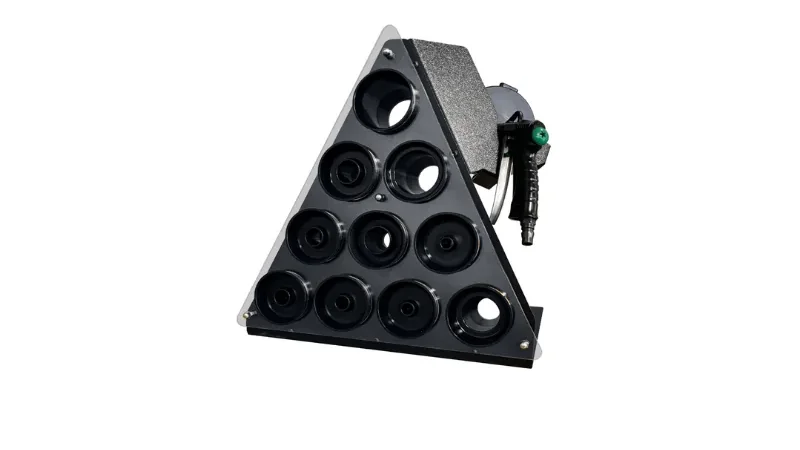
The Engineering Behind a Crimp — Why the Die Profile Matters
Wikipedia's article on crimping explains the process clearly: crimping joins ductile materials by deforming them past their yield point to create cold-weld tension and static friction. Unlike soldering or brazing, "because no alloy is used, the joint is mechanically stronger." The deformation has to be neither too light (leaving voids and incomplete cold-flow) nor too strong (causing deformation damage).
That is where the die comes in. The die geometry determines the final crimp profile. Variations include hexagonal, square, trapezoidal, bowl, flat, and stepped profiles. Each profile is engineered for a specific ferrule shape. A die that physically fits the machine but has the wrong profile cannot produce the correct cold-weld — it leaves voids inside the crimp or over-compresses the ferrule, damaging the wire reinforcement.
| Crimp quality | What the die did | What happens in service |
|---|---|---|
| Correct die, correct setting, first piece measured | Metal deformed past yield point; cold-weld formed; no voids. | Assembly matches hose pressure rating; defensible. |
| Wrong die profile (even if ID is close) | Uneven compression; voids on one side; over-compression on the other. | Assembly may pass visual but fail under pressure or impulse. |
| Under-crimp (insufficient force or setting) | Incomplete cold-flow; metal did not fully deform. | Pull-off force reduced; assembly may blow off under pressure. |
| Over-crimp (excessive force) | Over-deformation; wire reinforcement damaged; inner tube collapsed. | Assembly passes initial test but fails early under impulse. |
The Five Inputs That Decide Your Die Set
Input 1 — Hose Construction
| Hose type | Reinforcement | Die implication |
|---|---|---|
| SAE 100R1 / EN 853 1SN | One wire braid | Lower tonnage; usually no-skive. |
| SAE 100R2 / EN 853 2SN | Two wire braids | Workshop-standard tonnage. |
| SAE 100R12 / EN 856 4SP | Four spiral wires | Higher tonnage; skiving often required. |
| EN 856 4SH | Four spiral wires, heavy | Heavy-wall ferrule; high-tonnage machine. |
| SAE 100R13 / R15 | Four to six spiral wires | Mining class; dedicated heavy-duty dies. |
Input 2 — Fitting Series
| Fitting series | Die implication |
|---|---|
| One-piece no-skive | Integrated ferrule profile; die matches the integrated shape. |
| Two-piece no-skive | Separate ferrule; die matches the ferrule profile. |
| Skive-type interlock | Ferrule grips the wire directly; heavier die profile. |
| Field-attachable reusable | Usually no die; the fitting is threaded together. |
Input 3 — Uncrimped Ferrule OD
| What to measure | How |
|---|---|
| Uncrimped ferrule OD | Caliper at the ferrule's widest band, before crimping. |
| Ferrule length | Caliper along the crimp band. |
| Ferrule profile | Visual — straight, shouldered, stepped. |
Input 4 — Target Crimp Diameter
The target crimp diameter comes from the hose and fitting manufacturer's published data. It is the primary acceptance criterion for the finished crimp. Without it, the operator cannot verify the crimp, and the die choice is a guess.
Input 5 — Machine Interface
The die has to fit the machine. Two dies with the same ID and profile may have different cone angles, drive keys, or locator rings.
| Interface variable | What it must match |
|---|---|
| Cone angle | The machine's master die or conical piston. |
| Drive key or locator ring | The machine's die drive system. |
| Front-load vs side-load | How the dies are installed. |
| Die length | The machine's die opening depth. |
Hose ID Is Not Ferrule OD
This is the single most common die-selection error. A 1/2-inch hose ID does not mean a 1/2-inch ferrule OD.
| Hose size (nominal ID) | Typical ferrule OD range | Why the range |
|---|---|---|
| 1/2" (13 mm) | 18–22 mm | Depends on manufacturer and fitting series. |
| 3/4" (19 mm) | 24–29 mm | Same — manufacturer and series dependent. |
| 1" (25 mm) | 29–35 mm | Wider range because more fitting families are in play. |
| 1-1/4" (32 mm) | 36–44 mm | Same. |
| 1-1/2" (38 mm) | 42–52 mm | Same. |
Die Profiles: Bowl, Flat, Step
| Profile | Ferrule shape it matches | Why |
|---|---|---|
| Bowl (curved) | Shouldered ferrule, typical of one-piece no-skive fittings. | The curve follows the ferrule shoulder; produces even compression across the profile. |
| Flat (straight bore) | Straight ferrule, typical of two-piece fittings. | Uniform compression along a constant-diameter ferrule. |
| Stepped (two-diameter bore) | Ferrule with two diameters (heavy-wall front, thin-wall back). | Matches both diameters; common on interlock and high-pressure fittings. |
Using a bowl die on a straight ferrule, or a flat die on a shouldered ferrule, produces an uneven compression that can damage the wire reinforcement or fail to seal. The die profile must match the ferrule profile.
Die Length: Why Short Dies Cause Ovality
Die length is not a cosmetic variable. A die that is too short for the ferrule's crimp band produces an oval crimp, because the compression is concentrated in the middle of the ferrule and the ends are unsupported.
| Die length relative to ferrule | Result |
|---|---|
| Die length ≥ ferrule crimp band | Even compression; concentric crimp. |
| Die length < ferrule crimp band | Compression concentrated in the middle; ovality exceeds tolerance. |
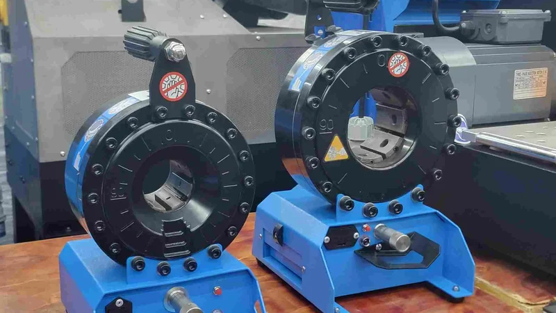
TRC Die Series
TRC crimpers use die series matched to the machine family. The die set is configured per order based on the customer's hose and fitting systems.
| TRC machine class | Die series | Coverage |
|---|---|---|
| TRC P10HP / P16HP / P18HP (manual) | Compact die series | 1/4"–1" braided; some 4SH. |
| TRC P20 / P20S / P20D | P20 series | 14 standard dies (P20/14 through P20/47), covering 14–52 mm crimp diameters; 4 optional dies for extended range. |
| TRC P32 / P32A / P32D | P32 series | Larger ferrule OD; up to 2" R13. |
| TRC P140 / P160 / P175 | Industrial die series | Large-bore industrial ferrules. |
See the hydraulic hose crimper category for the machine lineup. Die sets are configured per order.
First-Piece Control: The Check That Saves the Batch
Once the die is installed and the setting is made, the first piece of every batch must be measured.
| Measurement | Tool | Acceptance |
|---|---|---|
| Crimp diameter at the flat band | Caliper (0.02 mm) | Within manufacturer's published target. |
| Ovality (three positions around circumference) | Same | Within manufacturer's limit. |
| Three positions along the crimp length | Same | Within published taper limit. |
A Working Scenario — Not a Customer Case
An illustrative scenario. A workshop had the correct hose (1/2-inch 2SN) and the correct fitting (one-piece no-skive), but the operator loaded a die stamped for a different fitting family of the same nominal size. The die ID was close — within about 0.3 mm of the correct die — but the profile was different.
The first-piece crimp diameter measured within tolerance, because the target happened to fall in a similar range. What the operator did not catch was that the die profile produced uneven compression across the ferrule shoulder. Under impulse testing, six of ten assemblies developed micro-leaks at the stem, because the upper portion of the ferrule was under-compressed.
The root cause was not the die ID; it was the die profile. The lesson is that the die has to match the full component system — hose, fitting, ferrule, target diameter, and profile — not just the nominal size.
Frequently Asked Questions
How do I know which die to use?
From the hose and fitting manufacturer's published crimp data. The correct die is the one whose ID, profile, and length match the hose, fitting, ferrule, and target crimp diameter called out in the data sheet.
Can I use a die from a different manufacturer if the ID is the same?
Usually not. The ID is one of several variables. The die profile, length, and machine interface also have to match. A die from a different system may physically fit the machine but produce an uneven or undefendable crimp because the profile does not match the ferrule.
Why does my die produce an oval crimp?
Most commonly because the die is too short for the ferrule's crimp band, the profile does not match the ferrule shape, or the machine interface allows the die to rotate under load. Measure the ovality at three positions around the ferrule; if the ovality exceeds about 0.1 mm, the die or the setup is wrong.
Buyer question: what do I do if my crimper has no die chart?
Ask the hose and fitting manufacturer for the validated die + target diameter combination for your specific hose and fitting. We can also help match TRC die sets to your component references through the contact page.
References and technical boundaries
- ISO/TS 17165-2:2018 — Hydraulic hose assemblies, practices. Supports the controlled-system principle.
- Wikipedia — Crimp (joining)). Reference for the cold-welding principle, die geometry, and failure modes.
- Wikipedia — Die (manufacturing)). Reference for the general definition of die tooling.