Hose Ferrule Crimping Tool and Fitting Compatibility
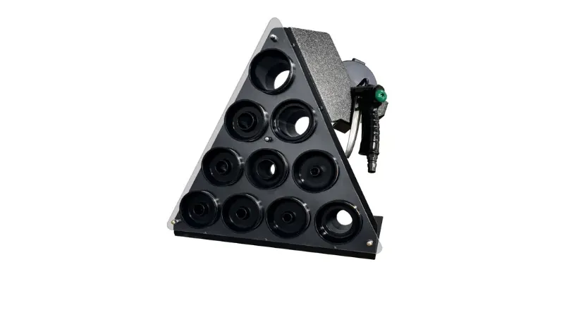
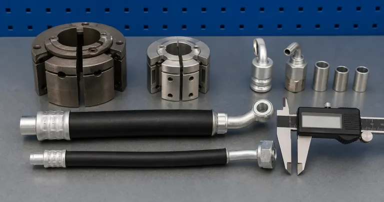
A hose ferrule crimping tool cannot be chosen by the ferrule’s outside diameter. Two ferrules with identical OD can sit on different stems, mate with different hoses, and require different dies to produce a defensible crimp. The mistake of picking a tool by ferrule size alone is one of the most common causes of mixed-system failures in hose assembly.
This article explains the four parts that must agree before any hose ferrule crimping tool can produce an acceptable crimp: the hose, the fitting stem, the ferrule, and the die. We also cover the engineering behind why a ferrule is not just “a metal ring” — the cold-welding principle, the mating geometry, and the system-specific design all determine whether the finished assembly is defensible or defective.
A Ferrule Doesn’t Decide the Tool; the Assembly Does
The ferrule is one part of a four-part controlled system. Wikipedia defines a ferrule as a ring or cap attached to an object to prevent damage, fraying, or splitting, and in the context of hose coupling, the ferrule is the component that the crimper physically deforms to lock the hose and fitting together.
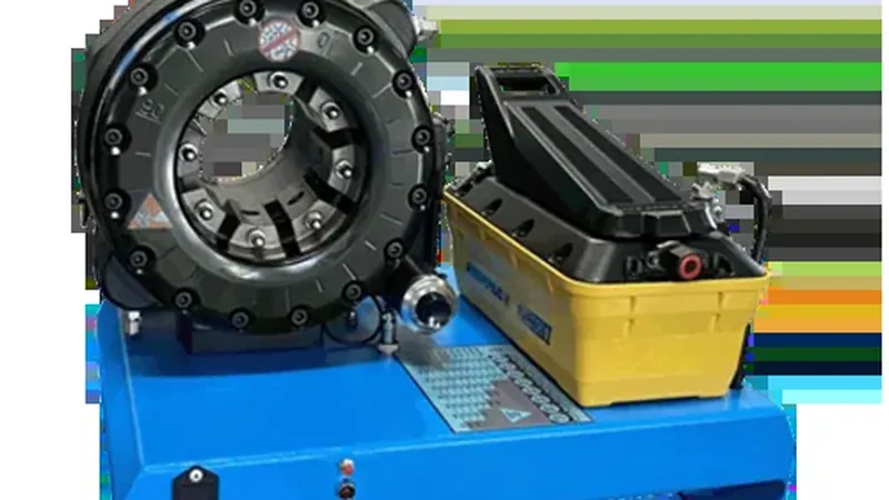
The hose and fitting manufacturer publishes a crimp instruction that ties a specific hose to a specific stem, a specific ferrule, a specific die, and a specific target crimp diameter. Change one of those four parts without re-validation, and the published target diameter no longer applies.
| Part | What it brings to the assembly | What changes if you swap it |
|---|---|---|
| Hose | Carries the fluid; its reinforcement (braid or spiral) provides the pressure rating. | Different reinforcement changes the die profile and the skive requirement. |
| Fitting stem | Seats inside the hose ID and forms the primary seal; its serrations engage the inner tube or wire layer. | Different stem profile changes the target diameter and engagement depth. |
| Ferrule | Surrounds the hose OD and the stem; deformed inward during crimping. | Different ferrule OD or wall changes the required die ID and tonnage. |
| Die | The segmented tooling that closes around the ferrule; its profile and length set the crimp geometry. | Different die profile produces a different crimp even at the same target OD. |
The tool is the last decision in the chain, not the first. Once you know the hose, stem, and ferrule, the die and the target crimp diameter follow from the component manufacturer’s data sheet.
The Cold-Weld Physics: Why a Crimped Ferrule Outperforms a Compression Fitting
The Wikipedia article on crimp joining) describes the underlying mechanism in one sentence that is worth unpacking in detail: an effective crimp deforms the metal past its yield point so that the compressed material causes tension in the surrounding connector, creating high static friction between the parts. That sentence carries three engineering concepts, and the ferrule is the component that delivers all three.
The first concept is the yield point. Steel and brass ferrules behave elastically under low load. Push a little, and they spring back. Push past the yield point, and the deformation becomes permanent. The crimp stroke is sized to take the ferrule wall well past yield into plastic deformation, so the finished shape does not relax back when the dies retract.
The second concept is residual tension. After the dies retract, the ferrule tries to spring back elastically but cannot, because it has been plastically deformed. The result is a state of internal tension in the ferrule that clamps down on the hose reinforcement and the fitting stem. That clamp load is what resists pull-off under pressure pulses.
The third concept is static friction. The clamping force generates friction between every contact surface: ferrule-to-wire, wire-to-wire, stem-to-inner-tube, stem-to-wire. Static friction is what holds the assembly together under axial load. The friction force equals the normal force times the coefficient of friction. Increase the clamp load, and the friction resistance rises with it.
The combination of yield-point deformation, residual tension, and static friction produces what crimp literature calls a cold weld. No heat is applied. No filler alloy is used. The ferrule and the wire reinforcement are forced into intimate contact under pressure high enough to cold-flow the metals together. The bond is gas-tight, meaning oxygen and moisture cannot reach the interface to cause corrosion. The joint is mechanically continuous.
| What happens during crimping | The engineering result |
|---|---|
| Ferrule wall compresses inward | Grips the hose outer cover and bites into the reinforcement. |
| Hose deforms | Outer cover pushed inward; wire reinforcement partially compressed; inner tube squeezed against the stem. |
| Stem serrations engage | Either bite into the inner tube (no-skive) or directly into the wire layer (skive); forms the primary mechanical lock. |
| Cold-weld forms | Metal deformed past yield point; tension and static friction lock the assembly without alloy or flame. |
When all three are correct, the finished crimp has a mechanical lock that resists pull-off, a pressure seal between the inner tube and the stem, and a clean deformation that does not damage the wire reinforcement. Get one wrong and you get leakage (seal failed), blow-off (lock failed), or a hose that passes the first pressure test but bursts early under impulse (wire damaged).
Crimped Ferrule vs Compression Fitting: Two Different Sealing Mechanisms
Buyers sometimes confuse a crimped ferrule with the ferrule inside a compression fitting. The two are different sealing mechanisms, and they are not interchangeable.
| Attribute | Crimped ferrule (permanent hose assembly) | Compression fitting ferrule (tube fitting) |
|---|---|---|
| Installation | Hydraulic crimper with matched die set; one-time plastic deformation. | Wrench tightening of a compression nut; ferrule swages onto the tube as the nut is torqued. |
| Deformation mechanism | Radial segmented dies close on the ferrule in a single controlled stroke; cold-weld formed. | Compression nut drives the ferrule into a converging seat; ferrule bites the tube as the nut torques down. |
| Removability | Permanent. The ferrule is destroyed if removed. | Theoretically removable, but the ferrule is usually discarded after disassembly. |
| Pressure class | Up to 6,000 psi working pressure (mining and aerospace hose). | Typically up to 1,000–3,000 psi depending on tube and ferrule material. |
| Application | Permanent hydraulic hose assemblies. | Metal tubing in fluid and gas systems (water, fuel, instrumentation). |
A compression fitting relies on the wedging action of a ferrule driven into a seat by a nut. The seal is formed at the seat and at the bite into the tube wall. A crimped ferrule relies on radial plastic deformation that grips the hose reinforcement and the fitting stem. The two systems share the word “ferrule,” but the physics, the tooling, and the application are different.
A hose ferrule crimping tool cannot be used to install a compression fitting ferrule. A compression nut and wrench cannot be used to install a hose crimp ferrule. The two ferrule categories look similar from the outside; the tooling makes them different.
Hose Coupling Mating Geometry: Why “Same OD” Is Not “Same System”
The Wikipedia entry on hose couplings makes a point that drives the entire tool-selection process: coupling systems rely on highly specific mating geometries, and incompatibilities exist even within the same nominal sizes. A “1-inch ferrule” is not a single thing. It is one of several mating-geometry families, each with its own stem profile, its own die series, and its own target crimp diameter.
| Coupling family | Mating geometry | Ferrule / crimp tooling implication |
|---|---|---|
| One-piece no-skive (braided hose) | Stem and ferrule pre-assembled; ferrule grips cover plus reinforcement. | Matched die series; no skiving; lower tonnage. |
| Interlock (spiral hose, skived) | Outer cover removed; ferrule grips wire directly; stem serrations also engage wire. | Skive band required; matched interlock die series; higher tonnage. |
| Two-piece stem + ferrule | Separate stem and ferrule that the assembler mates on the hose. | Tooling must match both parts; ferrule positioning is critical. |
| 4-bolt flange | Flange with O-ring face; ferrule or flange is crimped onto the hose. | Flange-crimp die series; squareness critical to flange mating. |
| JIC 37° flare | Threaded fitting with machined flare; thread carries the seal. | Crimp attaches ferrule; thread engages the flare. |
When a buyer orders “a 1-inch ferrule crimper” without naming the coupling family, the supplier cannot know whether the tooling should be no-skive, interlock, two-piece, flange-crimp, or JIC. Each family uses different dies, different target diameters, and different tonnage classes. The ferrule OD is the entry point to the discussion, not the conclusion.
The Four Parts in Detail
The Hose
| Hose type | Reinforcement | Implication for the ferrule tool |
|---|---|---|
| SAE 100R1 / EN 853 1SN | One wire braid | Lower tonnage; usually no-skive. |
| SAE 100R2 / EN 853 2SN | Two wire braids | Workshop-standard tonnage; covered by 137-ton class. |
| SAE 100R12 / EN 856 4SP | Four spiral wires | Higher tonnage; skiving often required. |
| EN 856 4SH | Four spiral wires, heavy | Heavy-wall ferrule; demands high-tonnage machine. |
| SAE 100R13 / R15 | Four to six spiral wires | Mining class; dedicated heavy-duty tool. |
The Fitting Stem
| Stem type | How it seals |
|---|---|
| No-skive, one-piece stem + ferrule | Stem serrations bite into the inner tube; ferrule grips the outer cover. |
| No-skive, two-piece (stem + separate ferrule) | Same engagement, but the ferrule is a separate part that must be matched to the stem. |
| Skive-type interlock | Outer cover removed; the ferrule grips the wire reinforcement directly. Stronger lock; higher pressure class. |
The fitting manufacturer publishes the target crimp diameter for each stem + hose + ferrule combination. That target is the only defensible acceptance window for the finished crimp.
The Ferrule
| Ferrule variable | What it affects |
|---|---|
| Uncrimped OD | Decides the minimum die ID that will accept the ferrule before crimping. |
| Wall thickness | Decides the tonnage required to reach the target diameter. |
| Length | Decides the required die length; short dies produce oval crimps. |
| Profile | Decides the required die profile (bowl, flat, stepped). |
| Material (steel, stainless, brass) | Decides yield strength; a softer material reaches yield at a different stroke. |
The Die
| Die variable | What it must match |
|---|---|
| Cone angle / drive key | The machine’s master die or piston geometry. |
| Die profile | The ferrule profile. |
| Die length | The ferrule’s crimp band. |
| Die ID stamping | The published die ID for the hose + fitting combination. |
A die from a different system, even if it physically fits the machine, does not produce a defensible crimp unless it has been validated against the specific hose + stem + ferrule combination.
One-Piece vs Two-Piece Fittings
| Fitting type | Construction | Tooling implication |
|---|---|---|
| One-piece (integrated shell) | The ferrule is pre-positioned on the stem; the assembler inserts the hose and crimps. | Tooling must match the integrated profile; simpler assembly but less flexibility. |
| Two-piece (separate stem + ferrule) | The ferrule slides over the hose before the stem goes in; the assembler positions it and crimps. | Tooling must match both parts; more flexible but requires careful ferrule-stem matching. |
The Target Crimp Diameter: Where It Comes From
The target crimp diameter is the finished OD the ferrule must reach after crimping. It is published by the hose and fitting manufacturer, and it is the primary acceptance criterion for the finished assembly.
| Source | What it gives you |
|---|---|
| Hose/fitting manufacturer’s crimp data sheet | Target diameter, tolerance (typically ±0.05 mm), measurement position, die ID. |
| Online crimp database (component manufacturer) | Ties hose + fitting + crimper + die to a published instruction. |
| Printed crimp chart (wall poster) | Bench reference for the above. |
The target diameter is not something you measure on an uncrimped ferrule and reproduce. It comes from the controlled system documentation.
Tool Selection: From Four Inputs to Die ID
| Step | Input | Output |
|---|---|---|
| 1 | Hose part number + construction | Pressure class; skive requirement. |
| 2 | Fitting stem part number + series | Stem profile; engagement mechanics. |
| 3 | Ferrule part number + measured uncrimped OD | Minimum die ID; tonnage requirement. |
| 4 | Published target crimp diameter | Acceptance window for the finished crimp. |
| 5 | Manufacturer’s die ID for the above combination | The die to load into the machine. |
TRC Die Sets and Machines for Ferrule Crimping
TRC crimpers use die series matched to the machine family. The die set is configured per order based on the customer’s hose and fitting systems.
| TRC machine class | Die series | Typical coverage |
|---|---|---|
| TRC P10HP / P16HP / P18HP (manual) | Compact die series (P10, P16, P18) | 1/4″–1-1/4″ braided; some 4SH. |
| TRC P20 / P20S / P20D (137 ton) | P20 series | 14 standard dies (P20/14 through P20/47), covering 14–52 mm crimp diameters. |
| TRC P32 / P32A / P32D (200 ton) | P32 series | Larger ferrule OD range; up to 2″ R13. |
| TRC P140 / P160 / P175 | Industrial die series | Large-bore industrial ferrules. |
If you are working with a specific hose + fitting system and you are not sure which die set you need, send us the part numbers and the uncrimped ferrule OD. We can confirm the die series, die IDs, and target diameters. Start at the hydraulic hose crimper category. TRC equipment is built in a 5,000 m² CE/SGS/UL+ISO certified factory serving more than 300 customers across 50+ countries, with a four-hour response window on technical inquiries.
A Working Scenario — Not a Customer Case
An illustrative scenario. A workshop had a die set that produced an acceptable crimp on one manufacturer’s 1-inch 2SN hose with that manufacturer’s stem and ferrule (uncrimped ferrule OD 25.4 mm, target diameter 23.1 mm). When a second manufacturer’s stem was substituted to save cost, using the same nominal ferrule OD, the crimp diameter measured within tolerance — but the stem’s serration profile was different, engaging the inner tube at a different depth.
Under impulse testing, six of ten assemblies developed micro-leaks at the stem. The root cause was not the ferrule or the die; it was the stem substitution, which changed the engagement mechanics even though the outside geometry looked identical. The lesson is that “same OD” is not “same system.”
Frequently Asked Questions
Can I select a hose ferrule crimping tool by ferrule size alone?
No. The ferrule OD is one of four variables. The hose, stem, ferrule, and die form a controlled system, and the tool must be matched to the full system via the manufacturer’s published crimp data.
What is the difference between one-piece and two-piece hose fittings?
A one-piece fitting integrates the stem and ferrule into a single pre-assembled part. A two-piece fitting uses a separate stem and ferrule that the assembler puts together. The tooling has to match the chosen construction.
Can I use another brand’s ferrule on my hose and stem?
Not without re-validation. The manufacturer’s published target crimp diameter assumes the full set comes from one controlled system. A different-brand ferrule of the same nominal OD may have different wall thickness, profile, or material, which invalidates the published target.
What is the difference between a crimped ferrule and a compression fitting ferrule?
The sealing mechanism. A crimped ferrule is permanently deformed by radial segmented dies, producing a cold-weld bond between the ferrule, the hose reinforcement, and the fitting stem. A compression fitting ferrule is driven into a seat by a wrench-tightened nut, producing a bite seal on the tube wall. The two systems share the word “ferrule” but the physics, tooling, and application are different.
Buyer question: where does the target crimp diameter come from?
From the hose and fitting manufacturer’s crimp data sheet. It is the finished OD the ferrule must reach after crimping. It is not something you can derive by measuring the uncrimped ferrule.
References and technical boundaries
- Wikipedia — Ferrule. Reference for the general definition of a ferrule as a clamping ring.
- Wikipedia — Compression fitting. Reference for the role of ferrule-based compression seals and the distinction from crimped ferrules.
- Wikipedia — Crimp (joining)). Reference for the cold-welding principle, yield-point deformation, residual tension, and static friction.
- Wikipedia — Hose coupling. Reference for coupling mating geometries, the permanent vs reusable distinction, and the same-nominal-size incompatibility principle.
- ISO/TS 17165-2:2018 — Hydraulic hose assemblies, practices. Supports the controlled-system principle.