
How to Use a Hydraulic Hose Crimper: An 8-Step Workflow With Checks
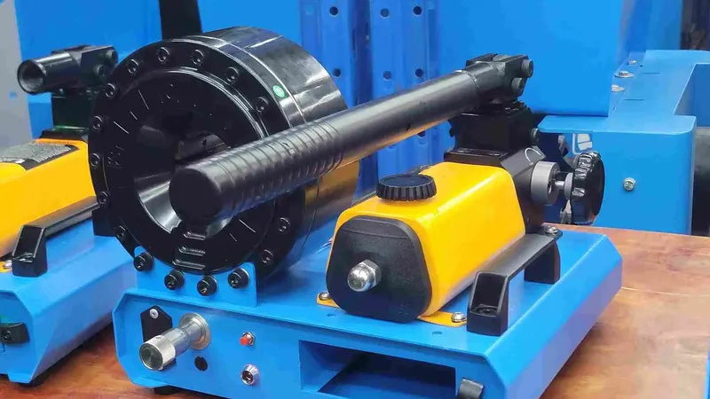
Learning how to use a hydraulic hose crimper is not about operating a machine. It is about running a controlled assembly process. Every step exists to catch one of the failure modes that show up later as leaks, blow-offs, or burst hoses under impulse. Skip a step, or do it without measuring, and the rest of the workflow cannot recover the lost information.
This article breaks the job into eight steps, in the order a workshop actually performs them. Each step has a job, a check, and a common mistake. The workflow applies to every TRC crimper format — hand-pump, powered electric, CNC, portable — because the physical process does not change when the power source changes.
The Force Physics That Makes the Workflow Possible
Before the steps, it helps to understand why a crimper can be operated by a single person and still produce hundreds of tons at the dies. A hydraulic hose crimper is a closed fluid-power system. Its force multiplication is governed by Pascal’s Law, published by Blaise Pascal in 1663. A pressure change at any point in a confined incompressible fluid is transmitted undiminished throughout the fluid in every direction.
The formula is short. Force equals pressure times area, written F = P × A. On the input side of a workshop crimper, a 3 kW electric motor drives a hydraulic pump that pressurizes oil to roughly 30 MPa. That pressure is transmitted unchanged to the master cylinder that drives the dies. The output force equals 30 MPa multiplied by the master cylinder area. Because the master cylinder is much larger than the pump piston, the output force is much larger than the input force.
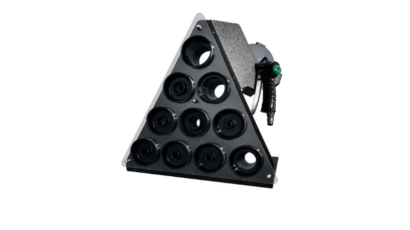
A worked example makes the multiplication concrete. On the TRC P20 workshop crimper, the 3 kW motor drives the pump to produce roughly 30 MPa of system pressure. That pressure acts on a master cylinder of approximately 4,500 mm² effective area, producing about 1,370 kN of axial force on the cone, which the segmented dies convert into roughly 137 ton of radial closure at the ferrule. The motor is rated at 3 kW. The output force is rated at 137 ton. The factor between them is the area ratio between the pump and the master cylinder.
Energy is conserved across this multiplication. The distance the dies move is inversely proportional to the area ratio, so the small input force moves a long distance and the large output force moves a short distance. That is why a crimper can generate 137 ton at the dies without a 137-ton motor. The hydraulic oil must be incompressible for the principle to hold; that is why the system uses oil rather than compressed air, and why any air trapped in the system must be bled before operation.
The same Pascal’s Law principle is what makes a hand-pump crimper like the TRC P16HP work. A 20 kg force at the lever, amplified by the pump’s mechanical advantage and then multiplied by the master cylinder area ratio, produces 95 ton at the dies. The operator feels the lever load. The dies feel a hundred tons. Both are real, and both are produced by the same physical law.
Step 1 — Confirm the Components and the Crimp Data
Before the hose touches the cutter, you need five pieces of information on the bench.
| Information | Where it comes from | Why it matters |
|---|---|---|
| Hose part number and construction | Hose label or reel tag. | Decides the die, the tonnage, and whether skiving is required. |
| Fitting part number and series | Fitting package or catalog. | Decides the target crimp diameter and the ferrule profile. |
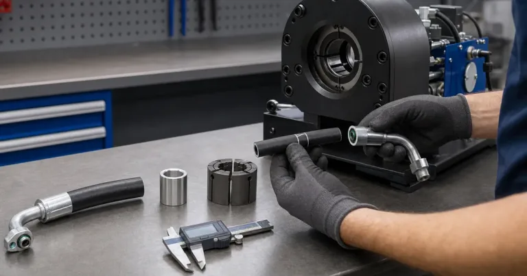
| Uncrimped ferrule OD | Measured at the bench with a caliper. | Confirms the ferrule matches the die; protects against mixed stock. |
| Target crimp diameter | Hose and fitting manufacturer’s crimp data sheet. | The acceptance window for the finished crimp. |
| Die identification | Die stamping or the machine’s die chart. | Confirms you are loading the die the crimp data calls for. |
The most common error here is assuming a “1/2-inch hose” is a single thing. A 1/2-inch SAE 100R2 braided hose, a 1/2-inch 4SH spiral hose, and a 1/2-inch air-conditioning barrier hose are three different crimping problems with different target diameters. The hose part number is the entry point, not the nominal size.
Pro tip. Print the crimp data for your five most-used hose and fitting combinations and tape them to the bench. The operator who has to walk across the shop to look up a target diameter is the operator who skips the check.
Step 2 — Cut and Prepare the Hose
The cut is a process step, not just a rough beginning. A square cut with a clean edge is required because the fitting seats against the cut face, and the cut length has to include the fitting insertion allowance.
| Cut quality | What it affects |
|---|---|
| Square (perpendicular) within about ±0.5° | Stem seats correctly; ferrule aligns; length is repeatable. |
| Clean edge, no loose wire strands | Loose strands can fold into the crimp and create a leak path. |
| No heat damage (abrasive cutters) | Overheated reinforcement loses temper and fails early. |
| Correct total length | Hose length must include the fitting insertion depth. |
For production work, a purpose-built cutter is the right answer. TRC’s cutter line covers the range. Abrasive cutting produces significantly more debris than blade cutting and is not recommended for hydraulic assemblies. The C300 covers up to 2 inches of 4SH braided hose on a single 300 mm blade, and the C520A extends the same blade-cutting principle to 6-inch industrial hose.
Step 3 — Insert the Fitting and Mark the Insertion Depth
The fitting stem goes fully into the hose until it bottoms against the inner shoulder of the ferrule. Two checks belong here.
- The stem is fully inserted. A stem that stops short leaves a gap between the inner tube and the stem, which becomes a leak path.
- The insertion depth is marked on the outside. Push the hose onto the stem, then mark the hose outer cover at the back edge of the ferrule with a paint marker or scribe line.
The mark does two jobs. It confirms at the bench that the stem is bottomed. And after crimping, the mark tells you whether the hose pushed back out during the cycle. If the mark has moved more than a millimeter or two, the fitting was not held correctly and the assembly should be remade.
Step 4 — Install the Correct Die Set
This is where mixed-system mistakes happen. A die set must match three things: the cone angle or die interface to the machine, the die length to the ferrule length, and the die profile to the ferrule shape.
| Check | What you are looking for |
|---|---|
| Die ID stamping | Matches the die called out by the crimp data. |
| Machine interface | The die seats cleanly in the machine head; locator ring or drive key matches. |
| Die length | Long enough to cover the full crimp band of the ferrule. |
| Die condition | No visible wear steps, no cracks, no impact damage. |
On a TRC machine, dies are organized by series. The TRC P20 die series covers 6–60 mm crimp diameters in 14 standard dies (P20/06 through P20/52), and the TRC P32 die series covers the larger range up to 87 mm. Die stamping is the reference; if the stamping does not match the crimp data sheet, do not run the assembly.
A worn die produces a crimp diameter that drifts. Typical Cr12MoV tool steel dies, hardened to HRC 58–62, last about 10,000–30,000 crimps under normal use. When a calibration sample drifts more than about 0.05 mm from the target, the die needs reconditioning or replacement.
Engineering note. If the die set came with the machine but you have no published crimp data for your specific hose and fitting, do not improvise. Ask the hose and fitting manufacturer for a validated combination, or contact us for die-matching support against your component references.
Step 5 — Set the Tonnage or Position
The setting method depends on the machine format.
| Machine format | How the crimp is set |
|---|---|
| Manual hand-pump (TRC P10HP, P16HP) | By feel and by counting pump strokes to die-to-die contact, then verifying with a caliper. |
| Powered hydraulic with manual valve (TRC P20, P32) | By die-to-die contact or by set hydraulic pressure. |
| CNC programmable (TRC P20D, P32D, TRC120L) | By entering the target crimp diameter or selecting a stored program. |
A CNC machine is not automatically more accurate than a manual one. Both produce the same crimp if the die and the setting are right. What a CNC machine gives you is repeatability across operator changes, faster changeover between hose sizes, and an electronic record that the setting was actually used.
Step 6 — Crimp
With the hose loaded, the die set confirmed, and the setting made, the crimp cycle is the short part.
| Action | Purpose |
|---|---|
| Position the assembly so the ferrule sits in the die band, square to the die face. | A tilted ferrule produces an oval crimp. |
| Close the dies until the set position is reached. | This is the crimping stroke. |
| Hold the set pressure for the dwell time in the manual (usually 1–2 seconds). | Allows the ferrule to settle into final deformation. |
| Release pressure and let the dies open fully before removing the assembly. | Removing under pressure can mark the ferrule. |
Cycle time depends on the machine. The TRC P20S runs about a 3.6-second cycle at 10 mm stroke; the standard TRC P20 runs about 10 seconds. Neither number tells you anything about quality on its own — cycle time is a capacity number, not a quality number.
Step 7 — Measure the First Piece
This is the step most often skipped, and the one that catches the most defects. Crimp-diameter measurement catches under-crimp, over-crimp, wrong die, and worn tooling in a single reading.
| Measurement | Tool | Acceptance |
|---|---|---|
| Crimp diameter at the flat band of the ferrule | Caliper (resolution 0.02 mm or better) or micrometer. | Within the hose and fitting manufacturer’s published target window. Typical tolerance is ±0.05 mm (±0.002 inch). |
| Three positions around the circumference (120° apart) | Same. | Ovality within the manufacturer’s limit, usually well under 0.1 mm. |
| Three positions along the crimp length (front, middle, back) | Same. | Within published taper limit. |
| First-piece only, before the batch is run | — | If the first piece fails, stop and adjust before continuing. |
A go/no-go gauge is a faster bench check for production work. It does not give a diameter reading, but it tells you in seconds whether the assembly is within the acceptance window. For high-pressure work, a go/no-go gauge plus a periodic caliper check on the first piece of every batch is a workable combination.
Step 8 — Inspect and Validate
After the first piece passes, the rest of the batch gets a visual inspection and a measurement on a sample basis.
| Check | Pass | Fail |
|---|---|---|
| Ferrule surface | Smooth, no cracks. | Cracks, splits, fish-mouth at the back edge. |
| Hose cover at the crimp | No tearing, no exposed wire beyond the ferrule. | Wire exposed; cover folded into the crimp. |
| Hose-to-ferrule mark | The scribe line from Step 3 has not moved. | Mark moved >1–2 mm → hose backed out during crimp. |
| Hose free length | Matches the assembly drawing. | Wrong cut length. |
| Functional test (when required) | Proof pressure held for 30–60 s at 2× WP. | Any seep, bulge, or movement. |
The functional test is not always required, but it is required for safety-critical applications, mining, and any assembly that will see impulse cycling above about 1,000 psi. For those, SAE J343 defines the proof and impulse conditions.
Why Each Step Exists: The Engineering Rationale
Each of the eight steps exists for a specific physical reason. None of them are paperwork. Removing any one of them removes the only check that catches its associated failure mode.
| Step | Engineering rationale | Failure mode it catches |
|---|---|---|
| 1. Confirm components | The hose, stem, ferrule, and die form a controlled system. A change to any one invalidates the published target diameter. | Mixed-system combinations that pass a visual check but fail under impulse. |
| 2. Cut and prepare | A square cut seats the stem; a clean cut removes wire strands that could fold into the crimp. | Skewed stems, leak paths from folded wire, length errors. |
| 3. Insert and mark | The stem must bottom against the ferrule shoulder to form the primary seal. The mark confirms the hose did not push back during crimp. | Shallow insertion (leak), hose push-back (lock failure). |
| 4. Install die | The die profile produces the cold-flow pattern the target diameter is built around. | Wrong die ID, oval crimp, drift over a batch. |
| 5. Set tonnage or position | The ferrule must reach the correct phase of plastic deformation. Under-set leaves residual voids; over-set damages wire. | Under-crimp (voids), over-crimp (wire damage). |
| 6. Crimp with dwell | Dwell allows the ferrule to cold-flow into final position before the dies retract. | Spring-back, incomplete void closure. |
| 7. Measure first piece | The crimp diameter is an indirect measurement of cold-weld completion. | Under-crimp, over-crimp, wrong die, worn tooling — all in one reading. |
| 8. Inspect and validate | Visual defects (cracks, exposed wire) and functional tests (proof pressure) catch what the diameter reading misses. | Ferrule cracks, cover tears, seal failures under pressure. |
The Skiving Decision
One workflow question comes up more than any other: does this hose need skiving before crimping? Skiving is the removal of a controlled length of the outer rubber cover so the ferrule can grip the wire reinforcement directly. The decision is dictated by the fitting system, not by the hose pressure class.
| Fitting system | Skive requirement | Why |
|---|---|---|
| One-piece no-skive fittings for braided hose (1SN, 2SN) | No skive. | The ferrule is sized to grip the cover plus reinforcement together. |
| Interlock fittings for high-pressure spiral hose (4SP, 4SH, R12, R13, R15) | External skive required. | The ferrule must reach the wire directly to develop the residual tension needed for the higher working pressure. |
| Two-piece fittings with separate shell and insert | Internal skive required (cover and tube both removed). | The shell and insert sandwich the wire between two metal surfaces. |
The decision tree is short. If the fitting is a no-skive one-piece design, do not skive. If the fitting is an interlock design for spiral hose, skive. If the fitting is a two-piece design, follow the manufacturer’s instruction for internal and external skive. Skiving the wrong hose wastes time and damages the reinforcement; not skiving a hose that needs it produces a crimp with insufficient pull-off resistance.
For production volumes above roughly 20 assemblies per week, a powered skiving machine like the TRC S50 (electric, up to 2-inch hose) or SH50 (manual, 1/4-inch to 2-inch hose) gives consistent skive depth and width that a hand knife cannot match. For low volumes, a sharp hand knife and a depth gauge work, but expect slower cycle time and higher scrap rate.
The Steps Most Shops Skip
A common pattern on the shop floor looks like this: the operator knows the hose size, picks a die by eye, inserts the fitting by feel, crimps to die-to-die contact, and judges the result by appearance. The first piece is not measured. The crimp data sheet is in a drawer.
| Skipped step | What it costs you |
|---|---|
| No component verification (Step 1) | Mixed-system combinations that fail under impulse. |
| No insertion-depth marking (Step 3) | Cannot detect hose push-back after crimp. |
| Die selected by eye (Step 4) | Wrong die ID, oval crimp, drift over a batch. |
| No first-piece measurement (Step 7) | A bad setting produces a bad batch with no early warning. |
| Visual-only acceptance (Step 8) | A significant fraction of defects pass visual inspection. |
None of these steps requires an expensive machine. They require a printed crimp data sheet, a paint marker, a calibrated caliper, and the discipline to do them on the first piece of every batch.
Picking the Right Crimper for Your Workflow
The eight-step workflow is the same on every format. What changes is how many assemblies per hour the line can produce, and how repeatable the setup is across operators.
| Workload | Recommended TRC format | Specific models |
|---|---|---|
| Field repair, <15 assemblies/day | Manual hand-pump | TRC P10HP (compact, 6 ton, anti-corrosion zinc-nickel alloy, 720-hour salt-spray tested); TRC P16HP (95 ton, 10-second cycle, lightweight, popular in Europe). |
| Workshop, 50–300 assemblies/day, mixed hose | Powered electric, 137 ton class | TRC P20 (3 kW motor, 137 ton, classic, simple, rare failure); TRC P32A (drawer-type die cabinet, caliper rack, value pick). |
| Production line, frequent changeover, traceable | CNC 137 ton and up | TRC P20D (CNC with stored programs, step crimping, pressure control); TRC P32D (CNC step crimping, 200 ton). |
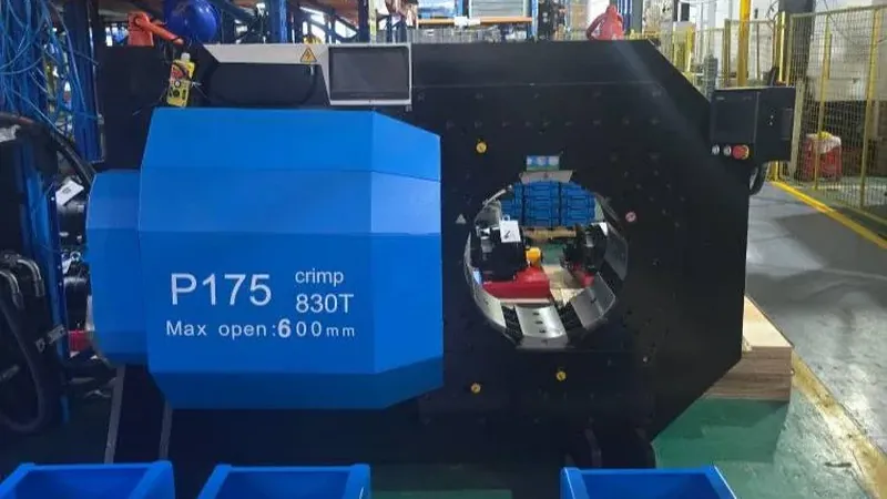
| Heavy-duty 2″–4″ R13, mining | 245 ton and up | TRC P140 (320 ton, separate power unit); TRC P175 (flagship 830 ton). |
The full range is in the hydraulic hose crimper category. If you are not sure which class fits your workload, the how to choose a hydraulic hose crimper resource walks through the buying decision as a checklist. All TRC crimpers ship from a 5,000 m² CE/SGS/UL+ISO certified factory and are backed by a four-hour response window for technical support to more than 300 customers across 50+ countries.
Frequently Asked Questions
Do I really need to measure the first piece every time?
Yes. A first-piece measurement takes about 30 seconds and catches wrong die, wrong setting, and worn tooling before they produce a bad batch. Skipping it means trusting the rest of the batch to visual inspection alone, which by published industry estimates misses a significant share of defects.
How do I know which die to use if my crimper has no chart?
Ask the hose and fitting manufacturer for a validated crimp instruction, which will name the die ID and the target crimp diameter for your exact combination. If neither the machine supplier nor the component supplier will publish the data, the safe answer is to not run that combination in a high-pressure circuit. We can also help you match TRC die sets to your component references — send us the hose and fitting part numbers.
Can I crimp in the field without a caliper?
You can, but you accept a higher defect rate. For field repairs, a go/no-go gauge sized to your hose and fitting system is a faster substitute for a caliper and catches the same major defects. For any assembly going into a high-pressure or safety-critical circuit, take the time to measure properly.
How can a 3 kW motor produce 137 ton at the dies?
Pascal’s Law. The pump pressurizes hydraulic oil to roughly 30 MPa. That pressure is transmitted unchanged to a master cylinder with a much larger effective area. The output force equals pressure times area, so a small pump force moving through a long stroke produces a large cylinder force moving through a short stroke. Energy is conserved across the multiplication. The 3 kW motor drives the pump; the dies see the multiplied force.
Buyer question: do I need a CNC machine to follow this workflow?
No. The workflow is the same on a manual hand-pump unit and on a CNC production machine. A CNC machine like the TRC P20D or P32D makes Step 5 (setting) and the batch record easier, but it does not remove the need for Step 7 (first-piece measurement). The workflow is a discipline, not a feature.
References and technical boundaries
- ISO/TS 17165-2:2018 — Hydraulic hose assemblies, practices. Supports the controlled-system principle and the requirement for first-piece verification.
- SAE J517 — Hydraulic Hose. Reference for SAE 100R hose specifications.
- Wikipedia — Crimp (joining)). Reference for the definition of crimping as a deformation-based joining process.
- Wikipedia — Die (manufacturing)). Reference for the role of dies in controlled deformation.
- Wikipedia — Pascal’s Law. Reference for the force-multiplication principle that underlies every hydraulic crimper format.
- Wikipedia — Skiving. Reference for the skiving process in hose preparation.