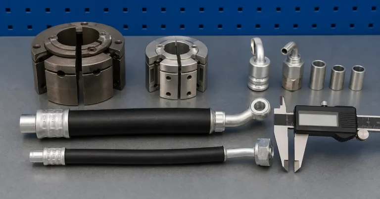
If you need to know how to crimp AC hoses correctly, treat the hose, fitting, sleeve, die and crimp instruction as one system. The steps below describe the control points. They do not provide a universal die number or finished diameter because those values depend on the component manufacturer.
In our review, the most expensive mistake is usually made before the handle or pump moves: the technician assumes that parts sharing a nominal size belong to one crimp system. We recommend stopping the job until the hose, fitting and sleeve identities agree with current assembly data.
A slow leak often starts before the crimper closes
A replacement hose fits the vehicle, but a slow refrigerant leak appears after installation. The root cause can sit anywhere from component mismatch and incomplete insertion to an incorrect die or unverified final crimp, so the assembly needs a controlled sequence rather than a visual-only check.
The workshop needs two separate approvals. First, the components and crimp must form a documented hose assembly. Second, a qualified technician must return the vehicle’s refrigerant system to service under the applicable procedure.
| Responsibility | Controlled by | Evidence |
|---|---|---|
| Hose, fitting and sleeve compatibility | Component-system data | Exact part references |
| Mechanical crimp | Machine, die and setting instruction | First-piece record and measurement |
| Refrigerant service | Vehicle/service procedure and applicable rules | Leak check and service record |
| Machine selection | Workpiece dimensions and workload | Model and tooling review |
Boundary: This article explains the mechanical hose-assembly workflow. Refrigerant recovery, charging and vehicle service require appropriate equipment, training and compliance with local rules.
Controlled AC hose crimping sequence
1. Identify every component
Read the hose marking and confirm whether it is standard barrier, reduced barrier or another specified refrigerant hose. Match the beadlock fitting and sleeve to that exact hose family and size.
Do not substitute hydraulic-hose fittings or use a fitting because the stem can be inserted.
Record the markings before cutting off a damaged section. Once the old end is discarded, the shop may lose the only readable hose identity.
| Part | Record before assembly | Stop condition |
|---|---|---|
| Hose | Manufacturer, series, size and barrier type | Marking or specification cannot be traced |
| Fitting | Part number, stem and tube geometry | Stem is selected only by physical fit |
| Sleeve | Part number, uncrimped OD and length | Sleeve family is unknown |
| Die | Identification and machine series | Die selected from nominal hose ID alone |
| Finished target | Value and measurement location | No current component instruction |
2. Cut the hose square
Use a suitable cutter that leaves the end square and limits loose debris. Inspect the bore and remove contamination using the component supplier’s procedure. Do not leave rubber or reinforcement fragments inside the line.

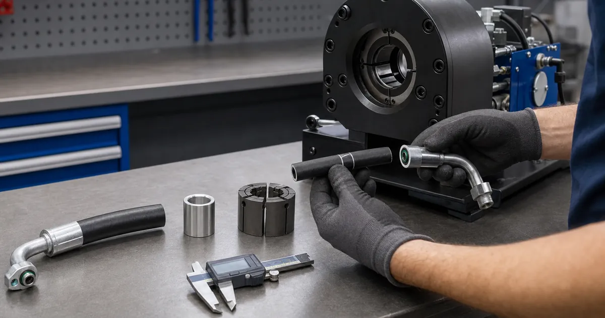
Do not use the bench image as an A/C component instruction. It illustrates the benefit of separating cutting, assembly and inspection positions.
3. Mark insertion depth
Measure the required insertion depth against the fitting and mark the hose. Push the stem fully into position without twisting or damaging the inner tube. Confirm the sleeve orientation before placing the assembly in the tool.
4. Select the specified die
Install the die identified for the hose-and-fitting combination. A beadlock AC hose crimper die should be selected from system data, not from hose ID alone.
Keep fingers clear of the closing zone. Stabilize a portable car AC hose crimping tool before applying force.
5. Apply the specified crimp
Position the sleeve at the defined location and close the tool using its operating instructions. Stop at the specified setting. Do not add extra compression because the sleeve “looks loose.”
Under-crimping may allow leakage. Over-crimping can damage the hose or fitting.
Keep the fitting supported while the sleeve closes. A long metal tube hanging from one side can pull the workpiece off axis. If the part moves, stop and inspect the setup rather than holding it closer to the closing dies.
6. Inspect the finished assembly
Check:
- insertion mark still shows full engagement;
- sleeve deformation is even;
- hose is not cut, pinched or displaced;
- fitting alignment is correct;
- measured dimension meets the component instruction.
Perform leak or pressure validation using the approved service procedure for the refrigerant system. SAE J2064 applies to coupled automotive refrigerant hose assemblies; meeting a hose requirement alone does not prove that the completed assembly meets the standard.
Measure at the stated location
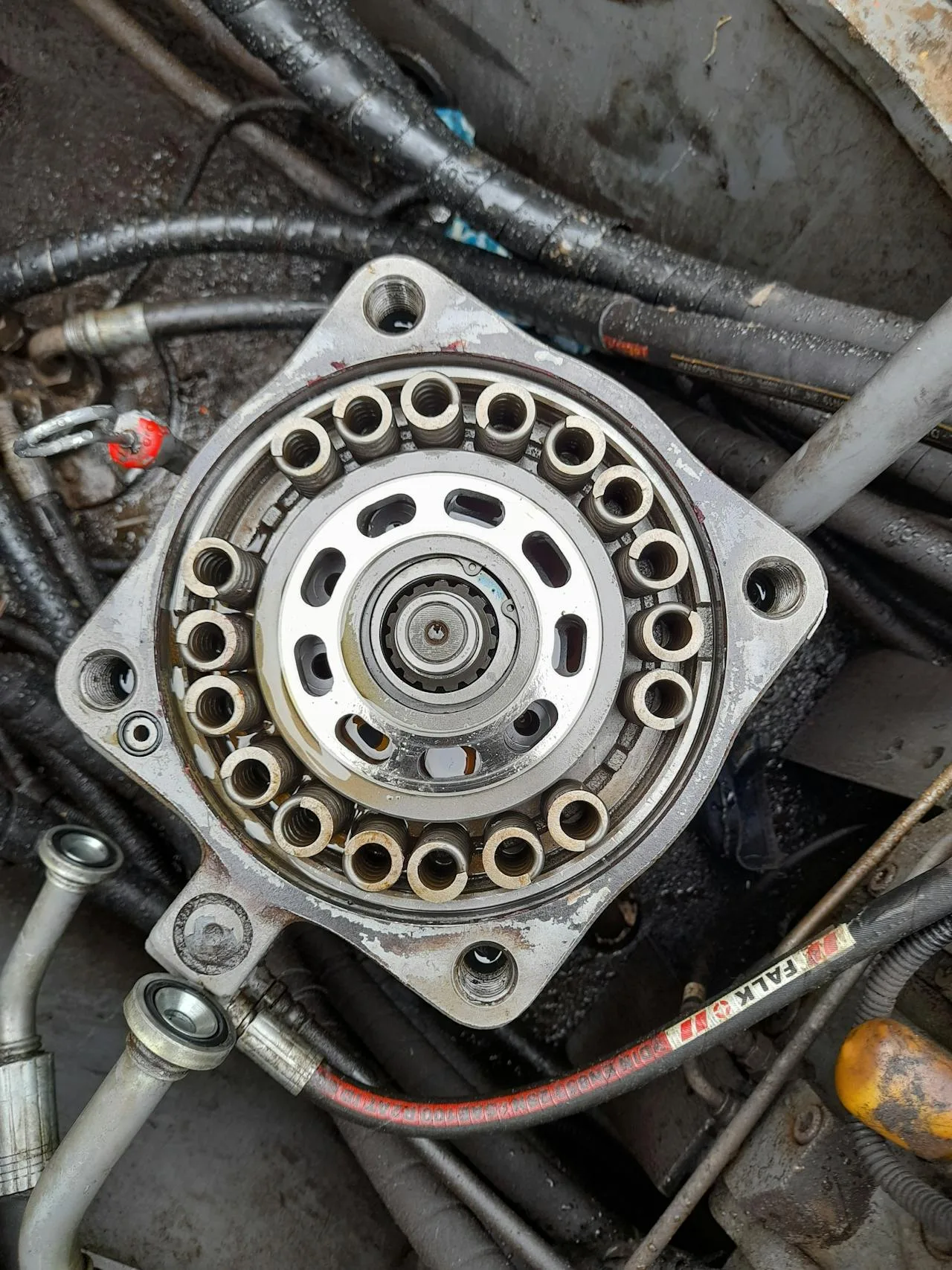
A caliper reading is useful only when the operator knows where to place it. Sleeve ends, formed ribs and the center of the crimp can produce different values.
Use the measurement location in the component instruction. Take readings around the sleeve if that method is specified, keep the caliper square to the axis and record the result without rounding it to “close enough.”
| Measurement mistake | What it changes | Correction |
|---|---|---|
| Measuring over a ridge or sleeve end | Reading may not represent the controlled zone | Use the specified location |
| Holding the caliper at an angle | Inflates the apparent diameter | Keep jaws square to the sleeve |
| Measuring only one side of a visibly uneven crimp | Hides out-of-round condition | Follow the required number and orientation of readings |
| Adjusting the machine before checking part identity | Treats the symptom, not the cause | Reconfirm components and die first |
Engineering note: Do not publish a universal finished diameter in a how-to article. The correct value belongs to the exact hose, fitting and sleeve system.
Can standard and reduced-barrier parts be mixed?
No general approval should be given. Their outside diameters and fitting systems can differ. Use a combination specifically documented by the hose-and-fitting supplier.
Record the first assembly before repeating it
A first-piece record does not need to be complicated. It should identify the hose, fitting, sleeve, die and machine setting, then show the insertion mark and the measured result. Record the measurement location because the middle of a formed sleeve and an uncompressed edge do not answer the same question.
Stop if the fitting moves during loading, the sleeve enters the die at an angle or the tool reaches the end of travel without meeting the specified result. Changing the setting without checking component identity can turn one bad assembly into a batch.
| Observation | Likely control to revisit |
|---|---|
| Hose pulls back from insertion mark | Stem insertion, sleeve position or handling during loading |
| One side collapses more than the other | Workpiece alignment, die seating or damaged tooling |
| Cover is cut or pinched | Wrong component/tooling combination or excessive compression |
| Finished dimension varies around sleeve | Measurement position, alignment or tooling condition |
| Assembly leaks after installation | Component match, insertion, crimp result and system test procedure |
Diagnose the failure in process order
If a new assembly leaks, begin at the records rather than immediately making a tighter crimp. Check hose identity, fitting and sleeve references, insertion mark, die and measured result.
An under-crimp can leave insufficient retention or sealing. An over-crimp can damage the hose or fitting. Both failures can look tidy from one angle.
For a production batch, quarantine the affected pieces and the components from the same setup. Do not let a second operator continue with an unverified adjustment.
Keep a first-off record that another technician can use
The useful record is short:
- Job or vehicle reference.
- Hose, fitting and sleeve identities.
- Die and machine setting.
- Insertion mark confirmation.
- Finished measurement and location.
- Operator and disposition.
Add a clear photograph when the fitting geometry is unusual. The record should let another trained technician reproduce the setup without guessing which die “looked right.”
Know where the crimper stops
TRC records the P70C dedicated A/C hose crimper with a 0.16–2 inch range and 20-ton maximum force. The product record states that it is not for hydraulic-oil hose.
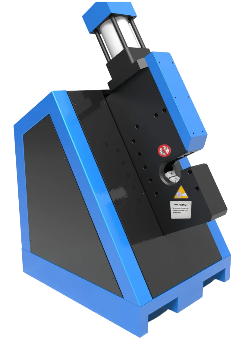
Those values help select the machine family. They do not replace the die schedule or the component supplier’s crimp target.
| P70C selection check | Evidence to send |
|---|---|
| Sleeve fits the working range | Actual uncrimped OD and length |
| Fitting can be loaded | Side photograph and distance to first bend |
| Die is available | Component row and requested tooling match |
| Workload suits the machine | Normal and peak accepted assemblies |
Treat refrigerant service as a separate responsibility
Crimping creates the mechanical joint. Evacuation, refrigerant handling, leak checking and return-to-service follow the vehicle and refrigerant service procedure. SAE J2064 covers coupled assemblies; SAE J3062 addresses the hose. Neither makes an undocumented field combination acceptable.
The US EPA motor-vehicle air-conditioning resources explain refrigerant and servicing responsibilities in the United States. Buyers in other markets should use the corresponding national rules.
Work through a leak investigation without guessing
A vehicle returns after an A/C hose replacement. The joint looks even, but the customer reports slow loss of cooling.
Start with the job record. Confirm the installed hose, fitting and sleeve identities, then compare the die and finished measurement with the current component instruction. Check the insertion mark and fitting alignment from the assembly photograph.
If the component row cannot be reconstructed, the shop has a documentation failure as well as a possible assembly failure. Do not solve it by applying another crimp to the installed sleeve. Remove and investigate the assembly through the approved service route.
| Evidence found | Next action |
|---|---|
| Wrong fitting or sleeve family | Replace with a documented component row |
| Insertion mark shows movement | Review insertion and loading method |
| Finished measurement outside target | Check die, setting, parts and measurement |
| Mechanical assembly passes records | Continue refrigerant-system leak diagnosis |
| No traceable record | Treat the assembly as unverified |
This scenario is based on the real user pattern “new hose leaks after crimping.” It is not a TRC customer case or a claim that every leak begins at the crimp.
Keep personal safety out of the line of fire
The closing head stores and applies considerable force. Keep hands outside the die area, support long fittings away from the closing zone and use the machine controls as instructed.
Do not use a finger to feel whether the hose has reached the stem stop inside an assembled fitting. Mark insertion depth before assembly. Do not hold a misaligned elbow closer to the dies during closure.
For the refrigerant side, follow the service equipment, ventilation and handling rules that apply to the refrigerant and market. The EPA MVAC program is relevant to United States service work; it is not a global substitute for local law.
Control rework and rejected parts
A sleeve that has been crimped and rejected should not go back into the good-component bin. Mark or destroy it according to the shop procedure so another technician cannot install it.
Keep rejected first pieces with the job record long enough to complete the investigation. Record whether the cause was component identity, insertion, tooling, setting, measurement or machine condition.
| Cause category | Corrective action |
|---|---|
| Wrong component | Fix storage, picking and job data |
| Wrong die | Improve identification and setup check |
| Incomplete insertion | Improve marking and operator method |
| Measurement error | Retrain and check instrument |
| Machine variation | Stop, inspect and service before production |
Repeat only after the first piece passes
For a batch, release one first-off assembly before cutting and crimping the entire order. This costs a few minutes and prevents the same incorrect setup from multiplying.
When the hose, fitting, sleeve, die or setting changes, make another first-off record. A color change or supplier lot may also require review if the component system instructs it.
At the end of the batch, compare a final piece with the first-off record. The purpose is to detect drift, not to create a claim that two matching readings prove every assembly.
Prepare the inquiry with real dimensions
If you need a beadlock AC hose crimper, send:
- hose marking and barrier type;
- fitting and sleeve part references;
- uncrimped sleeve OD and length;
- finished target and source;
- elbow or rigid-tube photographs;
- normal batch size;
- power available at the bench.
TRC can then check the P70C route and tooling question. Without these fields, any model answer remains provisional.
Set up the bench in process order
Place cutting and cleaning before component assembly. Keep identified fittings and sleeves in closed labeled containers, then position the crimper so the operator can support long tubes without reaching across the controls.
The measurement area should be clean and separate from cut debris. Put the component instruction where the technician can read it without leaving the workpiece unsecured.
| Bench zone | Required control |
|---|---|
| Incoming components | Identity remains visible |
| Cutting | Scrap and debris stay contained |
| Assembly | Insertion mark and sleeve orientation are checked |
| Crimping | Dies are identified and closing zone remains clear |
| Inspection | Measuring tool and record are ready |
| Rejected parts | Quarantine prevents reuse |
Handle a size change as a new setup
Return the previous die before opening the next component container. Clear loose sleeves and check that every segment of the new die belongs to the same set.
Make a new first-off assembly. A previous accepted setting for another hose size cannot release the next component row.
Protect finished assemblies before installation
Cap or protect prepared ends according to the component and service procedure. Keep the assembly identity with the job so it cannot be installed on the wrong vehicle.
If installation is delayed, store the hose without forcing a bend below its permitted route. Reinspect the sleeve and hose for handling damage before service.
Use one clear traveler from parts to vehicle
The job traveler should follow the assembly. Start it with vehicle or equipment reference and component identities, add the die and measurement at the bench, then record installation and service checks.
This prevents the technician from receiving an unmarked finished hose and asking which vehicle it belongs to. It also gives the shop a useful record if the vehicle returns.
Do not turn a how-to into a universal crimp chart
Readers often want one die number and one finished diameter. Publishing those without the exact hose, fitting and sleeve would create a dangerous shortcut.
The honest method is to show where the values come from and how they are recorded. The component system supplies the target; the machine and die reproduce it; the technician measures the result.
Review the process when any input changes
A different hose series, fitting revision, sleeve supplier, die or machine can change the assembly route. Stop and review current data.
Do the same after tooling damage or machine service. A previously accepted setting is evidence for its recorded conditions, not permanent permission.
Close the job with a specific disposition
Mark the assembly accepted, rejected or held for investigation. Do not leave a measured value in the record without a decision.
For accepted work, keep the component row and service record. For rejected work, identify the cause where possible and prevent reuse. For held work, name who will review it and what evidence is missing.
This small administrative step matters. A hose sitting on the bench with no disposition can re-enter production on the next shift.
Close the record only when every required mechanical and service check is complete. If the crimp passes but refrigerant service remains open, keep the vehicle job open. The workshop should never confuse a finished sleeve with a finished repair.
That final distinction keeps the mechanical assembly record honest and the vehicle service responsibility visible.
Keep both owners named.
A worked first-piece record for a repair shop
The first assembly of a new component family should leave a short paper trail. Record the hose and fitting references, sleeve reference, cut length, insertion mark, tool and die ID, specified finished measurement, actual measurement and final inspection result. If the component supplier calls for a leak test or another validation step, record that result as well.
Suppose an illustrative shop receives a reduced-barrier hose with a 90-degree compressor fitting. The operator cuts the hose cleanly but discovers during dry loading that the tube contacts the frame before the sleeve reaches the center of the dies. Pressing it at an angle would be fast, but it would make the result impossible to defend. The correct action is to change the loading route or tool configuration before crimping.
After a square loading trial, the operator marks insertion depth, assembles the components and confirms the mark has not moved. The first press is then measured at the location specified by the component data. If the reading is outside the stated requirement, the part is rejected and the operator checks die identity, component identity, setting and assembly sequence. A second uncontrolled press on the same sleeve is not a process correction.
Keep the accepted first piece and its record long enough to support the batch or repair file. When another operator takes over, the record shows what was used rather than relying on memory.
Warning: Refrigerant pressure, chemical compatibility and vehicle service procedures sit outside the crimping step. The completed assembly must still follow the responsible component and vehicle-system instructions. A correct sleeve measurement does not authorize evacuation, charging or service work by an unqualified person.
This disciplined first-piece routine adds minutes at the start and can prevent hours of rework after the line is installed in a crowded engine bay.
If the first piece changes after the machine warms or after a die change, stop and review the setup. Repeatability belongs to the complete process, not to one successful sleeve.
Frequently asked questions
AC hose crimping tools: what works for automotive A/C lines?
Use a tool and die package documented for the refrigerant hose, fitting and sleeve system you service. Manual equipment can handle occasional controlled work; a powered bench route makes more sense when repeat volume and operator effort justify it.
Can I use a hydraulic hose crimper for brake lines?
Do not treat hydraulic hose, A/C hose and metal brake tube as the same job. Use the fitting, forming tool and validation method documented for the exact brake-line system.
Need a machine for a documented A/C system?
Use TRC’s air conditioning hose crimper route and submit the component references. TRC can review machine and tooling fit; the hose-system data remains the authority for the finished assembly.