Pump oil into the pressure line
Each handle stroke moves a small volume of hydraulic oil. Leave enough sweep around the handle and keep the operator on stable footing.
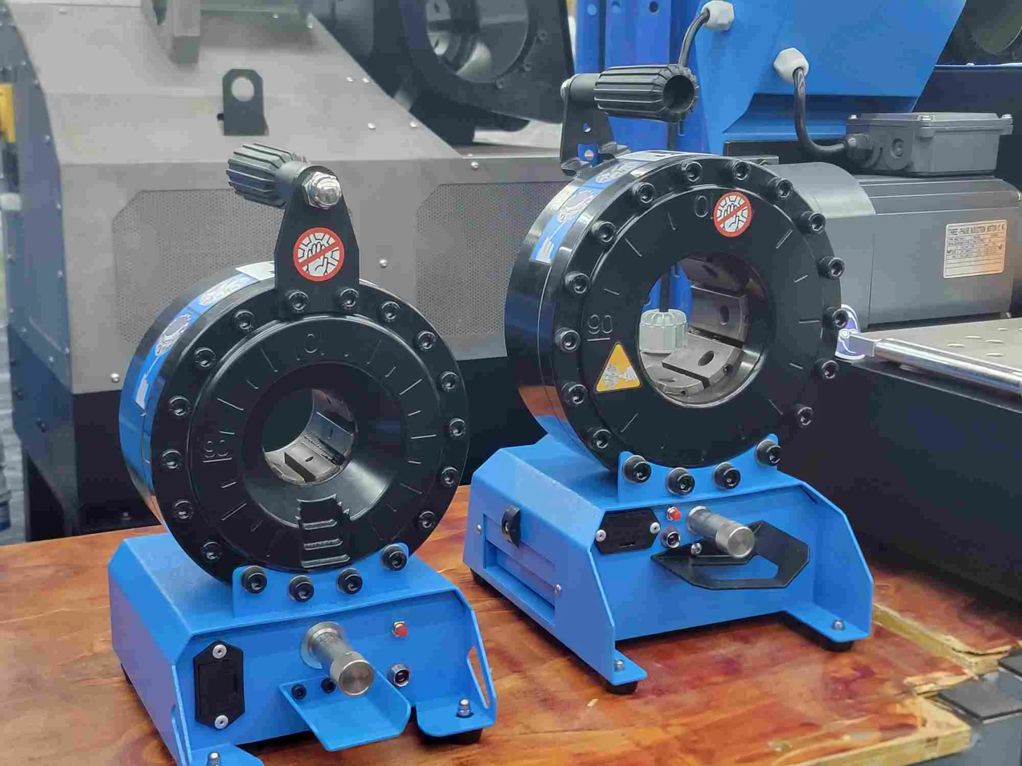
Compare TRC manual hydraulic hose crimper models by assembly range, pump layout, opening, weight and workload. Review built-in and separate-pump options.
No mains power | Built-in and separate-pump routes
A manual hydraulic hose crimper removes the need for mains electricity, but it does not remove the need for valid hose-and-fitting data, correct dies and finished-crimp measurement. TRC manual models range from the 3.5 kg P10HP for small-diameter work to P20-family machines for larger assemblies. Choose by actual ferrule diameter, opening, pump layout, machine weight and realistic daily workload.
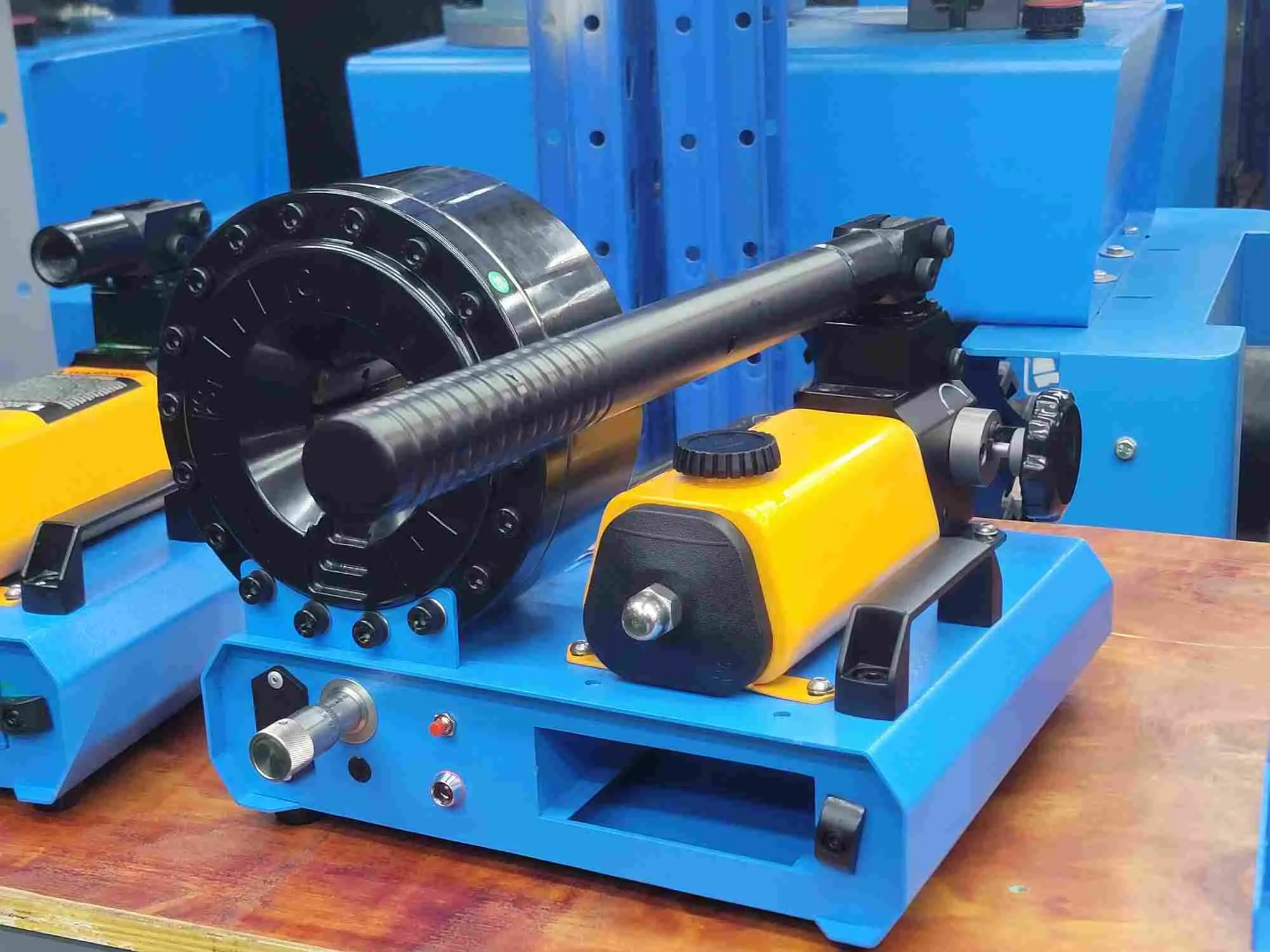
Buyers use manual hose crimper, manual hose crimping tool and manual hydraulic hose crimping tool for both integrated and split-pump equipment. A manual hose crimping machine can still weigh 85 kg, so the search wording “hose crimper manual” does not imply a handheld tool.
Manual does not always mean handheld
| Model route | Documented condition | Key limitation | Why consider it |
|---|---|---|---|
| P10HP | 1/4-inch small-diameter work; 10 ton; 3.5 kg net | Not a general hydraulic-hose workshop machine | Lowest transport burden for small hose, tube and A/C-type work within its documented range |
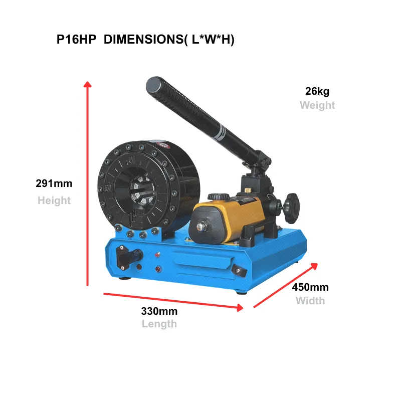
| P16HP | Up to 1-inch 2SP; built-in hand pump; 95 ton; 59 mm opening without dies | Hand pumping and P16 tooling range | Compact integrated route for lower-frequency field or repair work |
| P16HPZ | Up to 1-inch 2SP/4SP; separate hand pump; 95 ton; 24 kg net | Pump, hose and head must be positioned and transported together | Split layout improves positioning around elbows and constrained workpieces |
| P18HP | Up to 1-1/4-inch 4SP; built-in hand pump; 110 ton; 75 mm opening without dies; 40 kg net | Weight and operator effort are materially higher than P16 | Larger documented assembly range without mains power |
| P18HPZ | P18-family crimping range with separate hand pump | Independent dimensions are not fully recorded | Split layout where the P18 head and pump need flexible placement |
| P20LHP / P20LHPZ | Up to 1-1/2-inch 4SP/4SH; 185 ton; 109 mm opening without dies | Product record lists 85 kg net for the P20LHP route; plan lifting and transport | Larger manual range with built-in or split-pump choice |
| P20HP / P20HPZ | Up to 1-1/2-inch 4SP/4SH; 137 ton; 109 mm opening without dies | Product record states that the integrated P20HP requires two people to lift | Manual power for large assemblies when low frequency justifies the effort |
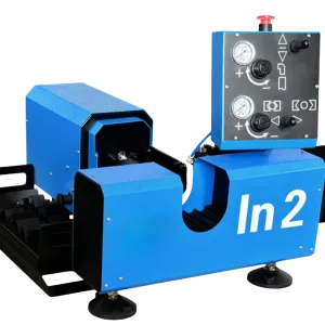
| IN2 | Product record states no electricity, portable construction and 1/4-to-3-inch range | Detailed force, opening, dies, dimensions and weight remain unverified | Keep as a conditional candidate only after sample and product-data confirmation |
Treat “portable” as a handling decision, not a marketing label. A machine that operates without electricity may still require two-person lifting, a trolley or permanent vehicle mounting.
Positioning decision
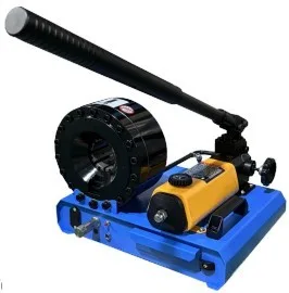
A built-in pump keeps the operating controls and crimping head together. It reduces the number of separate items to position, but the complete unit may be heavier and the handle path needs clear working space. Check whether the operator can load the assembly, pump and measure without twisting the hose or obstructing the fitting.
A separate pump allows the crimping head to be positioned closer to the workpiece and can help with elbows or restricted access. The hydraulic connection, pump stability and transport arrangement become part of the setup. A split machine is not automatically lighter overall; compare every component that has to be moved.
Hand-pump working path
Each handle stroke moves a small volume of hydraulic oil. Leave enough sweep around the handle and keep the operator on stable footing.
On a split system, place the pump and hose away from sharp edges, vehicle doors and foot traffic. A kinked or poorly supported line makes an otherwise compact setup awkward.
The crimping head converts hydraulic pressure into die movement. Support the assembly so the fitting enters square and the hose does not twist while the operator pumps.
Use the model’s return arrangement, remove the part without dragging it across the dies, and measure the first-off crimp before repeating the job.
Plan the working kit
| Setup item | What must travel or remain at the worksite | Selection check |
|---|---|---|
| Crimping machine | Integrated unit or separate head, pump and hydraulic connection | Total transported mass, stable mounting, handle clearance and safe lifting |
| Dies and tooling | Documented die series, supplied sizes, optional sizes and any adapters | Coverage of the actual ferrules and a storage method that keeps mating surfaces clean |
| Hose preparation | Suitable cutter and any preparation tool required by the component system | The field process must reproduce the specified cut, insertion and skive condition |
| Assembly components | Approved hose, fittings and ferrules with current crimp data | A broad machine range does not make unmatched field inventory valid |
| Measurement | Suitable calibrated measuring tool and the applicable target data | The first-off result can be checked at the specified positions |
| Work support | Stable bench, vehicle mount, stand or fixture for the machine and assembly | Long hoses and elbows do not pull the ferrule out of square during pumping |
| Cleanliness and protection | Defined post-cut cleaning method, caps or plugs and clean storage | Open hose ends remain controlled before installation |
For a split-head route, also plan where the pump sits, how the hydraulic hose is protected and how the head is restrained while the operator loads the workpiece. “No electricity” does not mean “no installation plan.”
Output without false promises
A manual machine can be a sound choice for emergency repair, farm or fleet maintenance and lower-frequency workshop work. It becomes less suitable when repeated pumping, frequent size changes or high daily demand creates operator fatigue and process variation. Finished output includes hose identification, cutting, cleaning, fitting insertion, die change, loading, crimping, measurement and records, including the seconds in which the dies close.
If regular demand makes the hand-pump step the bottleneck, compare the pneumatic or electric category using the same assembly and tooling requirements rather than choosing a larger manual machine by force alone.
Keep the process controlled
Before production or repair work, identify the exact hose, fitting and ferrule system, select the specified die, confirm insertion and preparation, make a first-off assembly and measure it at the required locations. If the pump feels abnormal, the dies do not reopen, or the measured result changes, stop and follow the model-specific operating and maintenance instructions. Do not publish one universal bleeding or adjustment procedure across every manual model.
The Gates Crimp Data and Dies Manual is a manufacturer-specific example of tying a machine, die and target measurement to a defined component system. Its settings are not TRC settings.
From the technical library
Use one checklist to confirm the workpiece, pump arrangement, dies, setup space and first-off inspection.
Open the setup checklistCompare the complete work cycle, operator effort and site dependencies instead of comparing closing time alone.
Compare manual and powered operationCheck where a compact hand-operated route is practical and where repeated work calls for powered equipment.
Check the workload boundaryThey can be suitable when the exact hose-and-fitting system is supported, the workload is low and the operator can cut, clean, assemble, crimp and measure consistently. A low purchase price does not replace valid dies, crimp data or inspection.
At minimum, plan the approved hose, fittings and ferrules, the required die set, a suitable cutter, contamination control, insertion and measuring tools, operating instructions and a defined inspection method. The list changes with the assembly program.
Choose a built-in pump when one-piece setup and storage matter. Choose a separate pump when head positioning, elbow clearance or split handling matters more. Compare total transported weight and connection layout, not the head alone.
Use the model-specific operating and maintenance instructions. Hydraulic layout, fill point and bleeding method can differ. Stop if the machine moves irregularly or fails to develop or release pressure; do not improvise a universal bleeding sequence from another model.
Move the comparison to electric or pneumatic when repeated pumping, regular daily demand, size changes or process-control requirements make manual operation the bottleneck. Confirm the same assembly range and tooling before changing the power route.
Manual route review
Send the hose and fitting references, ferrule OD, target crimp data, largest elbow, expected frequency and lifting or transport constraints. TRC will compare the built-in and separate-pump routes and identify any missing evidence.