
Hydraulic Steel Tube Crimper
Compare TRC hydraulic steel tube crimper models for cutting-ring fitting preassembly by tube OD, wall, material, component system and tooling.
Compare TRC hydraulic steel tube crimper models for cutting-ring fitting preassembly by tube OD, wall, material, component system and tooling.
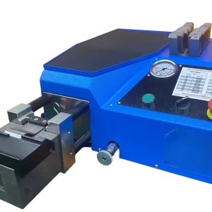
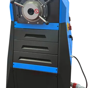
Two current routes | Machine-assisted cutting-ring fitting preassembly
A hydraulic steel tube crimper in this category is used to assist the preassembly of compatible cutting-ring tube fittings. The machine must be matched to the tube outside diameter, wall thickness, material, cutting ring, nut, fitting body and approved tooling. KT42 and KF42 cover different documented tube ranges, but neither should be selected from tube OD or a pressure number alone.
Send the tube specification, fitting-system reference, nut and cutting-ring details, required presetting instruction and representative samples before model confirmation.
Identify the connection correctly
A cutting-ring fitting is a flareless connection built around a fitting body, cutting ring and nut. During approved assembly, the ring engages the outside of the tube to create the required hold and sealing interface. Similar-looking metric, 37-degree flare and other compression connections use different geometries and instructions.
ISO 8434-1:2018 provides general and dimensional requirements for 24-degree cone connectors using cutting rings and related seal-cone designs within its scope. It also makes clear that application performance depends on multiple factors and requires sufficient testing and review. The standard does not make every tube, ring, nut, fitting or assembly machine interchangeable.
Name the connection before selecting the machine
| Connection route | What the operation changes | This category |
|---|---|---|
| Cutting-ring presetting | Drives a specified cutting ring into a prepared rigid tube in a controlled fitting system | Candidate route for KT42/KF42 only after the tube, ring, nut and system data are confirmed |
| Other compression fittings | Compresses an olive, ferrule or seal using the geometry defined by another fitting system | Requires separate system and tooling confirmation; do not assume compatibility |
| Flare fitting | Forms the end of the tube into a flare angle or profile | Not the same operation as cutting-ring presetting |
| Hydraulic hose crimping | Radially forms a ferrule around flexible hose and a hose fitting | Use the hydraulic hose crimper category |
| General swaging or tube end forming | Changes tube or sleeve geometry for a project-specific purpose | Requires application-specific tooling and validation outside a generic cutting-ring claim |
ISO or DIN terminology can describe a fitting family, but it does not certify KT42 or KF42 for every part made to that family. The exact tube, cutting ring, nut, fitting body and assembly instruction remain the controlling system.
Select from the complete component set
Compare documented tube ranges
| модель | Suitable condition | Documented processing range | Key limitation | Why recommend it | Product route |
|---|---|---|---|---|---|
| KT42 | General machine-assisted presetting within the documented tube range | Ø6 × 1 to Ø42 × 4 mm | Material, fitting system, tools and presetting instruction require confirmation | Broad documented OD route with simple operating position in the local product source | /products/6-to-42-mm-hydraulic-steel-tube-crimper-kt42/ |
| KF42 | Projects requiring review of heavier-wall combinations within its documented range | Ø6 × 1 to Ø38 × 6 mm, or Ø42 × 4 mm | The local “650 bar” record is ambiguous and must not be used as a universal connector rating or machine claim | Candidate for the documented heavier-wall range and applications needing a more demanding sealing review | /products/high-pressure-hydraulic-steel-tube-crimper-kf42/ |
KT42D appears in a combined local heading but has no separate current canonical product identity. K142 remains blocked because its record is mixed and unverified. Neither receives a separate public card in this plan.
Follow the responsible fitting instruction
Parker’s tube fitting assembly instructions illustrate the need for square cutting, deburring, cleaning, presetting and inspection in a defined fitting system. Use the instructions for their stated Parker components; do not transfer their settings to another system.
Start with the tube end
| Checkpoint | Review before the operation | Review after the operation |
|---|---|---|
| Tube identity | Material, OD, wall thickness, hardness or condition required by the fitting system | No mix-up between visually similar tube stock |
| Cut end | Square cut and sufficient straight length for the fitting instruction | No new distortion caused by handling |
| Burr and edge condition | Internal and external burrs removed as specified; end cleaned | No loose chips or sharp damage transferred into the fitting |
| Roundness and surface | Tube OD and surface are within the component-system requirement | No collapse, scoring or unintended marking outside the formed zone |
| Cutting ring, nut and body | Correct parts, orientation and size | Ring position and engagement match the responsible fitting instruction |
| Preset location | Tube fully inserted and correctly located in the tool | Required visible or measured inspection evidence is present |
Use a representative first article for every new tube and fitting program. If the cutting ring does not seat as specified, stop and check tube preparation, part identity, tooling and machine setup; do not increase force blindly.
Evidence before production release
The project evidence should include the tube specification, fitting-system data, selected tool, actual machine configuration, a first-off preassembly and the required inspection record. Photos should show the tube end before assembly, component identity, tool contact and inspected cutting-ring engagement—not only a finished nut from the outside.
For KT42 and KF42, review the tube-and-fitting documents, identified tooling and inspected first-off samples supplied for the specific project. Model-specific machine evidence should be confirmed during the quotation review; a hose crimper or generic pipe image is not a substitute.
Know when this category is relevant
| Situation | Page guidance |
|---|---|
| Metric 24-degree cutting-ring system with defined machine presetting tools | Relevant candidate; review tube, ring, nut, fitting and tool as one system. |
| JIC 37-degree flare connection | Different forming and inspection process; do not choose from this category without a verified compatible operation. |
| General plumbing compression fitting | Similar ferrule language does not prove compatibility with hydraulic cutting-ring tooling. |
| Unknown fitting found on existing equipment | Identify tube OD, thread, sealing geometry and manufacturer/series before selecting a machine. |
| Changed tube material or wall thickness | Recheck tool, process and qualification; do not reuse the previous setup automatically. |
| Route | Copy | Link |
|---|---|---|
| Hydraulic hose crimping | Use this route when assembling flexible hydraulic hose with a fitting and ferrule. | /product-category/hydraulic-hose-crimper/ |
| Complete equipment range | Compare tube, hose and supporting workshop equipment from the current catalogue. | /products/ |
| Technical review | Send the tube and fitting data for a KT42/KF42 compatibility review. | /contact/ |
Start with the exact fitting manufacturer’s instruction. Use the specified tube OD, wall and material; prepare the end correctly; install the correct nut and ring; use the approved presetting tool; and inspect the ring engagement at the stated stage. Excessive or incorrect assembly can damage the tube or component, while an incomplete preset may not create the required hold.
Do not identify it from one photograph alone. Record tube OD, thread, sealing geometry, cone/flare angle where applicable and any manufacturer markings. A 37-degree flare and a metric 24-degree cutting-ring system require different components and assembly processes.
No. The documented tube range is only an initial capacity boundary. The tube material and wall, fitting body, nut, cutting ring, presetting tool and assembly method must be compatible and reviewed together.
No. The cycle must produce the required preset condition, which then needs the specified inspection, final assembly and any application qualification. Machine movement alone does not establish connector performance.
Do not assume so. Material, tube condition and the fitting manufacturer’s rules can change the permitted components, tools or assembly process. Submit the new material and component system for a fresh review.
Tube fitting application review
Provide tube OD, wall thickness and material, fitting body, nut and cutting-ring references, the responsible assembly instruction, batch size and representative samples. TRC will compare the documented KT42 and KF42 ranges and list the tooling or qualification evidence still required.