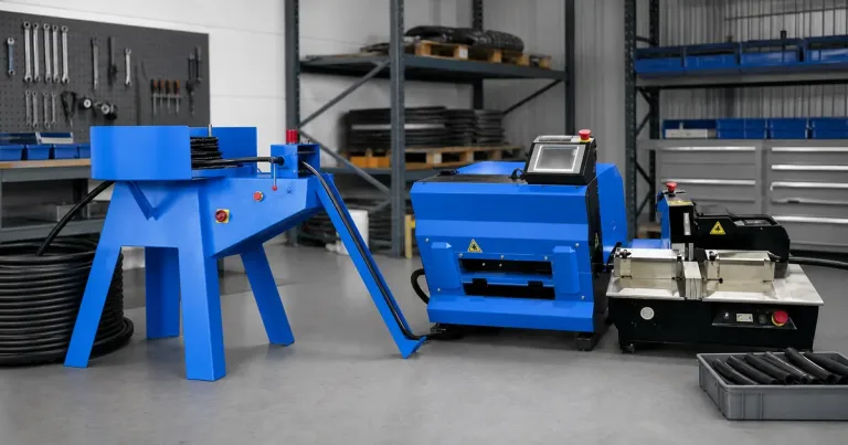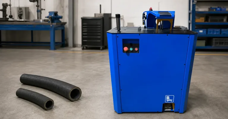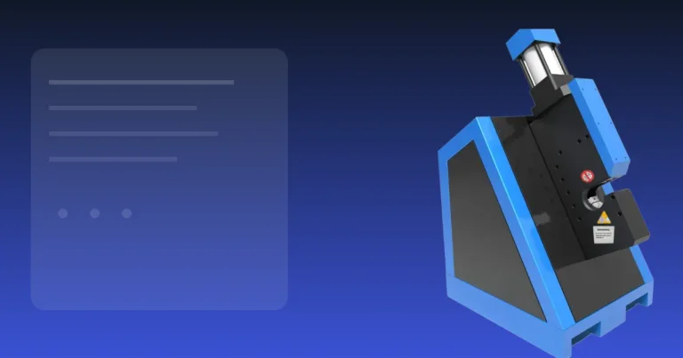

Une machine à couper les tuyaux prépare l'extrémité pour l'insertion du raccord et le sertissage. Le travail n'est pas terminé lorsque le tuyau se sépare. La coupe doit être suffisamment d'équerre pour le processus d'assemblage, l'alésage doit rester utilisable et les débris doivent être maîtrisés.
Les coupes en biais révèlent un problème de processus
Un atelier de tuyaux remplace une machine à couper usée suite à des plaintes concernant des extrémités en biais. La décision d'achat doit relier le coupeur à l'insertion du raccord, au nettoyage de l'alésage et à l'entretien de la lame, car une coupe rapide qui crée des reprises n'est pas productive.
Sélectionner en fonction du tuyau le plus dur
Fournir la construction du tuyau, le diamètre extérieur maximal et la fréquence prévue. Les machines à couper les tuyaux hydrauliques utilisées sur des tuyaux renforcés nécessitent une lame et un système d'alimentation adaptés aux couches de fils. Un coupe-tuyau hydraulique choisi pour une tresse légère peut ne pas convenir aux gros tuyaux multi-spirales.
Aménager la zone de travail
Soutenir le tuyau des deux côtés de la lame et maintenir la ligne de coupe stable. Utiliser les protections et les commandes comme prévu par le fabricant. Ne pas retirer une protection pour installer un tuyau plus gros ; cela signale un problème de capacité ou de maintien de la pièce.
Inspecter la coupe
Rejeter ou retoucher une extrémité lorsqu'elle présente :
- une coupe en biais hors de l'exigence d'assemblage ;
- un alésage pincé ;
- un fil tiré ou très effiloché ;
- du caoutchouc brûlé ;
- des débris libres qui n'ont pas été retirés ;
- des dommages empêchant l'insertion correcte du raccord.
Entretenir le système de coupe
Nettoyer la machine autour de la lame et de la zone d'alimentation. Inspecter la lame pour l'usure ou les dommages et utiliser la pièce de rechange spécifiée. Une force d'alimentation accrue, de la chaleur et des déchirures sont des signes d'avertissement pratiques.
Suivre les instructions de verrouillage et d'entretien du manuel de la machine. OSHA 1910.212 fournit un contexte général de protection, pas un substitut aux procédures spécifiques à la machine.
Garder le nettoyage et la vérification séparés
La méthode de coupe influence les débris, mais aucun coupeur ne doit promettre une propreté universelle. ISO/TS 18409:2018 décrit les méthodes d'échantillonnage pour l'analyse de la contamination par particules solides dans les tuyaux ou les assemblages de tuyaux. Il ne définit pas un processus de nettoyage universel ni une classe acceptable.
Élaborer une procédure post-coupe appropriée au système de composants et à l'utilisation finale.
Voir la Gamme de machines à couper les tuyaux TRC pour les formats disponibles. Envoyer des échantillons de tuyaux lorsque la construction ou l'adéquation de la lame est incertaine.
Utiliser les défauts comme déclencheurs d'entretien
Ne pas attendre que la lame cesse de couper. Suivre l'effort d'alimentation croissant, les cycles plus longs, la chaleur, l'odeur, l'arrachement de fil et une face irrégulière. Un changement soudain après un remplacement de lame indique un problème d'identité, d'installation ou de mise en place ; une détérioration progressive suggère plus souvent une usure ou une contamination.
Tenir un court registre d'entretien avec l'identité de la lame, la date d'installation, les tuyaux traités et les défauts observés. C'est plus utile que de remplacer les lames selon un calendrier universel, car la charge de travail et le matériau diffèrent.
Adapter la machine au tuyau normal et aux cas limites
| Modèle | Voie normale à étudier | Lame enregistrée | Limite principale à confirmer |
|---|---|---|---|
| C250AC | Coupe compacte d'atelier 1 pouce | 250 × 3,5 × 32 mm | Triphasé 380 V dans la fiche produit |
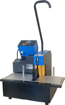
| C300 | Travail manuel 2 pouces 4SH | 300 × 4 × 32 mm | Alimentation par l'opérateur et support du matériau |
| C300A | Travail pneumatique 2 pouces 4SH | 300 × 4 × 32 mm | Alimentation en air 6 bars et configuration appropriées |
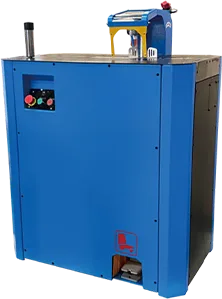
| C400F | Travail 2 pouces 4SH à pédale | 400 × 4 × 50 mm | Espace, protection et masse de la machine de 195 kg |
| C520A | Gros tuyau industriel jusqu'à 6 pouces | 520 × 4 × 50 mm | Ouverture de 132 mm et chemin de manutention complet |
Utilisez la catégorie coupeuses de flexibles hydrauliques pour comparer les voies, puis envoyer le tuyau normal le plus dur pour une coupe d'échantillon.
Maîtriser un changement de lame
Isoler la machine conformément à son manuel et à la procédure du site. Confirmer l'identité de la lame de rechange, le diamètre, l'épaisseur, l'alésage et le sens spécifié avant l'installation.
Après l'installation :
- Vérifier l’assise et la position du protecteur.
- Faire tourner ou tester uniquement comme le manuel le permet.
- Effectuer la première coupe représentative sans forcer l’avance.
- Inspect the face, bore, reinforcement and debris.
- Record the blade identity and acceptance result.
OSHA 1910.212 provides general guarding context. Machine-specific isolation and blade-change instructions still come from the manual and local safety procedure.
Règle d’atelier : If the replacement blade marking does not match the approved specification, stop. Similar diameter is not enough.
Measure the process that follows cutting
A cut-off machine can reduce cutting time while the shop still loses output at cleaning, insertion or inspection. Observe the full hose-assembly route.
Utilisation accepted cut pieces per hour = accepted pieces ÷ cutting-cell hours. Then compare it with accepted crimped assemblies per hour. If the cutter produces 40 accepted pieces and the crimping cell releases 20 assemblies in the same period, another faster cutter will not raise finished output.
This bottleneck example uses round numbers only to show the method. Replace them with one full shift of shop data.
Write the machine specification from the hose backward
Start with the hardest hose you expect to cut every week, not the largest size printed in a catalogue. We ask for its construction, actual OD, minimum bend condition at the machine, daily quantity and the end defect your assembly team will reject. That information determines the blade route, opening, support and feed method.
| RFQ field | What you should submit | Why it changes the choice |
|---|---|---|
| Hose identity | Family, reinforcement and actual OD | Separates light rubber work from wire-braid or spiral hose |
| Mode de travail | Normal batch, peak batch and changeovers | Shows whether manual feed is still practical |
| Cut acceptance | Squareness, bore and reinforcement limits | Gives the trial a pass or fail point |
| Services publics | Voltage, phase and available air | Prevents an unusable destination configuration |
| Downstream process | Cleaning, insertion and inspection route | Stops the cutter from being judged in isolation |
If you cannot identify the hose, send a marked sample. “Hydraulic hose” is not a blade specification.
Link cutting to fitting insertion
The useful cut is the one that lets the operator insert the specified fitting without hiding damaged wire or loose debris. During commissioning, take several accepted cut pieces through cleaning and fitting insertion. A clean-looking face that collapses during insertion is still a failed process.
We recommend keeping one accepted sample and one rejected sample at the cell. Photographs help, but the physical samples show the operator how an angled face, pinched bore or pulled wire actually feels during insertion.
Commission the complete cutting cell
Run a normal batch from coil handling through accepted parts. Record setup time, cutting time, rejected ends, cleaning time and operator corrections. This exposes whether the bottleneck sits at the blade, the material support or the next process.
Note d'ingénierie : Do not claim a production rate from blade movement alone. Accepted pieces per hour includes loading, measuring, cutting, handling and inspection.
A practical commissioning record contains:
- hose and blade identity;
- machine configuration and utilities;
- first-off result;
- defect count and reason;
- post-cut cleaning route;
- operator and approval date.
Repeat the first-off check after a blade change, a jam or a material change. You do not need a universal calendar. You need a trigger that operators can recognize.
Recover from a jam or abnormal cut
Stop and isolate the machine using its manual and site procedure. Do not clear a jam through an exposed blade path or compensate by pushing harder.
After the obstruction is removed, check blade seating, guard position, work support and the hose end. Run one representative sample before returning to production. If heat, smoke, wire pull-out or vibration remains, keep the machine out of service until the cause is identified.
The blade owner should also control the replacement specification. Diameter alone is not enough; thickness, bore, direction, speed and intended material all matter. OSHA’s interpretation on unsuitable cutting wheels addresses a different machine case, but the safety principle is relevant: a cutting tool must match the machine speed and intended use.
Compare a compact and a large cutting route
A compact shop processing mainly 1-inch reinforced hose can begin with the C250AC record: up to 1 inch 4SH, a 250 × 3.5 × 32 mm blade and 1.5 kW three-phase 380 V power. A shop cutting 2-inch 4SH should investigate C300, C300A, C400F or C400A according to feed method and utilities.
C520A is a different handling problem. Its product record covers industrial hose up to 6 inches, a 520 × 4 × 50 mm blade, 5.5 kW power, 6 bar air and a 132 mm opening. The hose support, operator path and floor space matter as much as the opening.
These are model facts, not a promise for every hose inside the nominal diameter. We still require a representative cut when construction or reinforcement is uncertain.
Hand the accepted process to production
The handover sheet should state the approved hose families, blade, guards, support arrangement, normal feed method, inspection points and stop conditions. Put the maintenance and blade reorder route beside it.
Review the process after enough real work has passed to show a trend. Use one locally chosen interval, then look at accepted pieces, blade changes and defects. A fixed “30-day” or “90-day” rule adds no value unless it matches the shop’s workload.
The final boundary should be plain: this machine is released for the listed hoses and setup. New hose constructions return to sample-cut review before routine production.
A maintenance record should explain the defect
A useful maintenance log does more than record that a blade was replaced. It connects the hose, symptom, inspection and corrective action. Without that chain, the next shift sees the same torn wire and changes another blade without knowing whether support or feed caused the problem.
| Observation | Premier contrôle | Ne supposez pas |
|---|---|---|
| Cut face wanders | Hose support and blade seating | The motor lacks power |
| Wire pulls from the end | Blade condition and match to reinforcement | All spiral hose behaves this way |
| Rubber smears or burns | Edge condition, feed and heat | Faster feed will clear it |
| Bore closes | Workholding and support | Cleaning can restore the shape |
| Debris rises suddenly | Blade damage and cutting setup | A stronger air blast solves the cause |
We recommend attaching a photograph of the cut face to the record when a defect first appears. Use the same angle and include the hose identification. That gives maintenance something more useful than “bad cut.”
Separate cleaning from cutting correction
Loose particles must be removed through the approved post-cut process, but cleaning does not correct a pinched bore, heat damage or pulled reinforcement. Reject the cut first, then clean the accepted replacement.
If the end-use specification calls for particulate verification, define the sampling method and acceptance authority in the quality plan. ISO/TS 18409:2018 addresses collection of contamination samples from hydraulic hose and assemblies. It does not prescribe one universal shop-cleaning method.
Give purchasing the real consumable requirement
When the first machine is ordered, ask for the fitted blade specification, one planned replacement route and the information needed to reorder it. The request should include diameter, thickness, bore and machine model. Do not rely on an unlabeled spare wrapped inside the crate.
For a C520A route, the product record states a 520 × 4 × 50 mm blade. That fact still needs to remain with the C520A asset; it should not be copied to another cutter because both machines happen to process large hose.
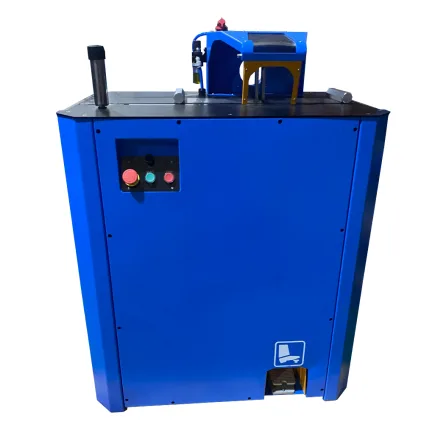
The same record should state who can release a new blade, where accepted spares are stored and what first-off test follows installation. That is enough control for a small shop without turning the job into paperwork for its own sake.
Foire aux questions
What is the best cutter for a reinforced hose?
There is no answer without the hose construction and workload. The correct machine uses an approved blade, holds the hose without crushing it and produces an acceptable sample under guarded operation.
Build the maintenance scope into the quotation
Ask TRC for the proposed blade specification, replacement route and sample-cut acceptance points together with the machine quotation.