
Una cortadora de manguera grande no es simplemente una máquina pequeña con una abertura mayor. La manguera reforzada de gran tamaño modifica la carga de la cuchilla, el manejo de la pieza de trabajo, la protección y la cantidad de residuos generados.
Seleccione por construcción y diámetro exterior real, no por una etiqueta indefinida de “servicio pesado”. Una afirmación de cortadora de manguera para servicio pesado necesita una construcción de manguera y una condición de prueba declaradas.
Una lista de mangueras mixta expone los límites de manejo
Un distribuidor quiere una cortadora para manguera de servicio pequeña y manguera industrial grande ocasional. El diámetro exterior más grande es solo un dato: la rigidez, el refuerzo, el manejo de la bobina, la exposición de la cuchilla y el soporte del operador pueden decidir si una máquina es práctica.
Cuando el tamaño se convierte en un problema de proceso
La manguera industrial de gran diámetro puede ser difícil de apoyar en escuadra con la cuchilla. Su peso y resistencia a la flexión pueden desviar la línea de corte. El refuerzo de múltiples capas también aumenta el calor y la carga de corte.
Una cortadora de manguera pequeña puede ser práctica para material flexible, de menor diámetro exterior y trabajo ligero. Se convierte en la elección incorrecta cuando el operador debe forzar la manguera, retirar las protecciones o hacer cortes parciales repetidos.
Compare las condiciones de trabajo
| Condición | Cortadora pequeña | Cortadora grande |
|---|---|---|
| Manejo de la pieza de trabajo | A menudo manual | Puede necesitar mesas o soporte guiado |
| Carga de la cuchilla | Menor en manguera blanda/pequeña | Mayor en manguera grande reforzada |
| Espacio | Compacta | Envolvente operativo más grande |
| Avance | Avance manual simple | El avance controlado puede ser más importante |
| Residuos | Menor volumen | Requiere recolección y limpieza planificadas |
Estas son diferencias generales. Use los datos del producto para cualquier afirmación de capacidad.
“Servicio pesado” necesita una definición
Pida al proveedor que identifique:
- construcción y diámetro exterior máximos de manguera probados;
- especificación de la cuchilla;
- requisitos de potencia y servicios;
- método de avance y sujeción;
- protección;
- mantenimiento esperado;
- criterios de aceptación de corte de muestra.
No acepte solo el diámetro interior de la manguera. Los diámetros exteriores de la férula y la manguera pueden ser mucho mayores que el diámetro nominal.
Seguridad del operador
La manguera grande puede almacenar energía de flexión y desplazarse durante el corte. Apóyela en ambos lados, siga el manual de la máquina y mantenga las manos fuera del punto de operación. OSHA 1910.212 establece los requisitos generales de protección de máquinas.
Ruta de selección
Use el categoría de cortadoras de mangueras hidráulicas para comparar formatos disponibles. Para una aplicación grande, envíe una muestra de manguera representativa. Una prueba de corte debe verificar la escuadra, la condición del diámetro interior, el refuerzo y el calor antes de aprobar el equipo.
Planifique la ruta del material alrededor de la máquina
La manguera grande puede luchar contra el operador antes de llegar a la cuchilla. El material curvo necesita espacio para enderezarse, y un tramo de corte pesado necesita soporte después de la separación. Si alguno de los lados cuelga de la cuchilla, el corte puede desviarse y el material puede moverse inesperadamente.
Dibuje la ruta de entrada y salida con la huella de la máquina. Marque dónde se sitúa el operador, cómo se soporta la manguera y dónde se recogen las piezas cortadas. Esto a menudo revela que una máquina con capacidad de diámetro adecuada sigue siendo un mal ajuste para el espacio disponible en el suelo.
Defina el punto de aceptación antes de la prueba
El gran tamaño puede hacer que un extremo rugoso parezca inevitable. No es una regla de aceptación útil. Decida qué necesita el proceso de ajuste posterior: ángulo permisible, condición del diámetro interior, contención del refuerzo, ausencia de daño por calor y manejo de residuos. El proveedor puede entonces elegir el soporte y la cuchilla en función de un resultado visible.
Cuando enviar una muestra es difícil, envíe una sección transversal etiquetada, información de diámetro exterior, pared y refuerzo, más un video que muestre cómo se comporta la manguera al enderezarse. Una revisión remota es más débil que una prueba de corte, pero es mucho mejor que seleccionar solo por el tamaño del diámetro interior.
Compare las rutas registradas de manguera grande
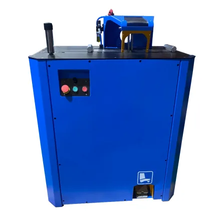
| Modelo | Alcance registrado de mangueras | Cuchilla | Alimentación o control | Registro de la máquina |
|---|---|---|---|---|
| C400F | Hasta 2 pulgadas 4SH | 400 × 4 × 50 mm | Pedal de Pie | 5 kW; 195 kg neto |
| C400A | Hasta 2 pulgadas 4SH | 400 × 4 × 50 mm | Pneumatic pusher, 6 bar | 5.5 kW; 197 kg net |
| C520A | Hasta 6 pulgadas de manguera industrial | 520 × 4 × 50 mm | Pneumatic pusher, 6 bar | 5.5 kW; 132 mm opening without dies |
The C520A record also lists a 900 × 650 × 1,150 mm machine size. These fields help with floor planning; the buyer still needs a cut trial on the actual hose.
Revise el C400F foot-pedal route, C400A pneumatic route y C520A large-diameter route against the same sample and acceptance sheet.
Support the hose before and after the blade
A six-inch industrial hose can be difficult to control even when it fits the opening. Coil memory, mass and stiffness can rotate the stock during feed. The operator should not become the missing support stand.
| Handling point | What to provide | Failure if omitted |
|---|---|---|
| Entrada | Level support aligned with the cutting plane | Hose twists or drags |
| Avance | Controlled push and a defined hand position | Unstable pressure near blade |
| Cut-off side | Support for the planned piece length | Part drops or tears at completion |
| Scrap area | Clear container away from controls | Debris accumulates around machine |
| Long-stock path | Floor space without vehicle or pedestrian conflict | Material blocks the aisle |
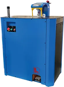
Nota de ingeniería: Maximum hose diameter is a fit check. It is not proof that the shop can load, support and remove the hose safely.
Measure production with the material path included
Use accepted cuts per hour = accepted pieces ÷ total elapsed hours. Start the clock when the operator retrieves and aligns the hose. Stop it after end inspection and debris handling.
An illustrative 10-piece trial may take 22 minutes including alignment, cutting and inspection. That is 27.3 accepted cuts per hour before normal interruptions. Replace these inputs with your own trial; the example is not a machine rating or customer result.
Run the trial with the largest normal coil and longest normal cut. A short straight offcut hides the handling work that often controls large-hose output.
Define acceptance before the sample arrives
Photographs alone are weak evidence. Ask the supplier to label the hose, blade, machine and trial conditions, then inspect:
- cut squareness;
- bore deformation;
- pulled reinforcement;
- heat marks;
- loose rubber and wire;
- operator intervention;
- cutting and cleanup time.
If the application has a cleanliness requirement, keep cutting and cleaning as separate controls. ISO/TS 18409:2018 describes sampling methods for solid-particle contamination analysis; it does not certify a cutting machine as clean.
Draw the large-hose cell to scale
The C520A enclosure is only one rectangle in the layout. Add the longest incoming stock, operator position, support stands, cut-piece length, scrap handling, control access and maintenance clearance.
For a coiled hose, draw the coil or payout stand as well. The material should enter the blade without crossing a pedestrian route or pulling sideways on the workpiece.
| Layout dimension | Buyer supplies | Supplier reviews |
|---|---|---|
| Incoming hose length and coil size | Normal and maximum | Entry support |
| Finished cut length | Normal and maximum | Exit support |
| Hose OD and bend behavior | Samples and photos | Opening and feed |
| Available aisle | Floor drawing | Safe access assumptions |
| Air and electrical points | Site data | Utility connection |
| Extraction or cleanup | Requisito en obra | Optional equipment and interface |
Compare foot-pedal and pneumatic feed by operator movement
C400F and C400A share a recorded 2-inch 4SH hose scope, 400 × 4 × 50 mm blade and 5.5 kW motor. The operating route differs.
With foot-pedal operation, review how the operator holds and supports the hose while using the control. With pneumatic feed, review air preparation, regulator setting, pusher travel and safe loading.
Neither system removes the need for entry and exit support. Pneumatic feed should reduce uncontrolled hand force, not pull an unsupported coil through the cell.
Work through a large-hose purchase example
Assume a distributor cuts 2-inch 4SH every day and receives a six-inch industrial hose request once every two months. C400F or C400A matches the recorded daily size route. C520A reaches the larger recorded industrial-hose scope.
Purchasing should calculate the margin and delay on the rare six-inch work, then compare outsourcing with the added machine, floor and air requirements. If the large hose becomes a strategic weekly service, the answer can change.
This example does not assign prices or production rates. It shows why the largest inquiry should not automatically determine the machine.
Set a support rule for short and long pieces
Short offcuts can rotate or fall near the blade. Long pieces can lever against the cutting plane. Define how both are held without placing hands near the point of operation.
Use a marked safe zone on the floor and a defined scrap container. During commissioning, observe where the operator naturally reaches. If that position crosses the hazard zone, redesign the support before production.
Plan blade replacement and access
A 520 mm blade requires a different handling plan from a compact 250 mm blade. Confirm isolation, guard removal, lifting or handling needs, storage and the exact replacement specification.
Do not stack large blades where edges can contact each other. Keep the machine reference with the spare.
Document the accepted envelope
After trials, state the approved hose references and the largest tested OD. Separate “recorded machine scope” from “buyer-tested materials.”
That distinction helps sales staff quote responsibly. A 6-inch product record is a selection field; the tested list is the evidence for the shop’s actual materials.
Manage coil and straight-stock deliveries differently
Coiled material needs payout and twist control. Straight large hose needs length, lifting and storage planning.
Ask suppliers how stock arrives and what minimum bend limits apply. Do not force a large stiff hose into a smaller floor area to match the machine.
Keep the operator away from suspended loads
If long or heavy hose requires mechanical handling, plan lifting points and support with qualified site personnel. Do not use the cutter table as an improvised lifting fixture.
The operator should control the process from a stable position outside moving material.
Review scrap and short remnants
Large hose scrap has weight and spring. Provide a container or rack that prevents pieces rolling into the aisle.
Label usable remnants with hose identity and length. An unmarked expensive offcut may later be mistaken for another construction.
Price the whole cell
Add machine, support stands, air preparation, electrical work, blade, optional extraction, packing, freight, unloading and commissioning.
large-hose cell cost = cutter + material handling + utilities + safety work + delivery + setup
The formula avoids comparing a bare C520A machine with a fully supported C400A cell as if the quotes were equivalent.
Review first-month bottlenecks
Track accepted cuts, handling time, rejects, blade observations and cleanup. If material payout controls the cycle, another faster cutting motion will not help.
If the rare six-inch hose still needs two people to guide it, redesign support before increasing volume.
Control the first and last meter of a coil
The outside wrap and tight inner wrap can behave differently. Include both in commissioning where practical.
Do not approve the machine from the easiest straight middle section. Record any extra alignment or support needed near the coil core.
Set a maximum manual-handling boundary
Use the site’s qualified safety review to decide when mechanical assistance or a second person is required. Do not invent a universal hose-weight threshold in the product page.
Write the boundary into the work instruction and provide the handling equipment.
Keep large-hose samples identified
Large black hose sections consume space and lose labels. Mark manufacturer, series, size and trial result on a durable tag.
Store accepted and rejected samples separately. Do not let a sales sample return to production stock.
Review air demand before choosing C400A or C520A
Both product records call for 6 bar supply to the pneumatic pusher. Ask the supplier for consumption and connection requirements.
Check pressure at the installed cell under normal plant demand. A compressor nameplate in another room does not prove stable supply at the machine.
Make receiving inspect the support equipment
Count stands, pneumatic parts, spare blade and extraction items beside the machine. Confirm damage and identity before installation.
A large cutter delivered without its planned entry support is not ready for commissioning. Record the shortage instead of asking operators to improvise with pallets.
Close the cell with a witnessed trial
Run the normal large hose and the edge-case sample with the final stands, air supply and operator position. Record first, middle and last cuts.
Purchasing confirms included equipment; engineering confirms cut and handling; operations confirms practical use. Keep open points off the production schedule.
Maintenance should join the handoff to confirm blade access, pneumatic service and replacement-part identity. Logistics should close package damage and missing supports before installation.
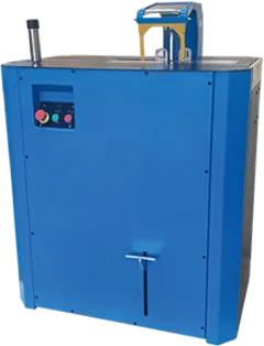
Plan the material path around a large hose
Large hose changes the workstation before it changes the blade. A stiff coil can push the operator off line, a long cut piece can pull on the work and a heavy offcut can drop as the cut finishes. We ask buyers to draw the path from storage to feed support, cutting zone, receiving support, inspection and cleaning.
Take the C520A as a planning example from the verified product record. It is listed for industrial hose up to 6 inches, with a 520 × 4 × 50 mm blade, 5.5 kW motor, 6 bar pneumatic requirement and 132 mm maximum opening. Those numbers describe installation and stated capacity; they do not prove every 6-inch construction will cut acceptably. Send the actual hose for a trial.
The layout must provide space around the machine’s recorded 900 × 650 × 1150 mm body plus the incoming coil and finished length. Check floor condition, electrical service, air quality and pressure, extraction needs, operator reach and a safe way to move large pieces. The receiving support should carry the offcut without pinching the blade or dragging the hose.
An illustrative industrial-hose shop may cut only eight large pieces in an hour. Saving two seconds of blade time has little value if two operators spend a minute lifting and realigning every piece. Better handling can improve accepted output and reduce awkward manual effort without changing the cutting head.
Layout rule: Ask the supplier for a sample-cut record and machine envelope, then design the material path at full hose length. A brochure photograph rarely shows the space required to handle the actual work.
Receiving inspection should repeat the difficult sample with the installed utilities and final work supports. Transport, electrical supply, air pressure and floor layout can alter how a large hose feeds. Keep the factory sample beside the destination result so any difference has a visible starting point.
Record the operator’s handling comments as well; measurements alone will not show an awkward lift, blind feed point or unstable offcut.
Preguntas frecuentes
How should a hose be cleaned after cutting?
Use the procedure required by the component system and end application. Protect the cut end after cleaning. If particulate cleanliness must be assessed, use an appropriate sampling and analysis plan; cutter size alone says nothing about cleanliness.
Review the complete handling setup
Send a hose sample, coil or straight-length details, cut length, batch size and available floor space through the página de contacto de TRC.